PDF p. 1339 · 24-69
Removal
- 1.Disconnect the negative battery cable and wait at least three minutes before beginning work.
- 2.Disconnect the airbag and seat belt tensioner connectors (See Page 24-23).
- 3.Remove the console assembly (see section 20).
- 4.Remove the SRS unit cover.
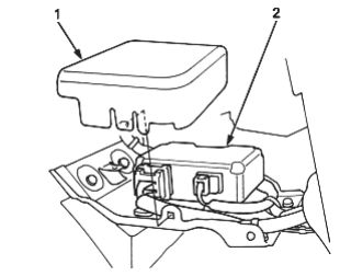
- 1. SRS UNIT COVER
- 2. SRS UNIT
- 5.Disconnect the SRS main harness 18P and main wire harness 8P connectors from the SRS unit.
- 6.Remove the four Torx bolts from the bracket then pull out the SRS unit.
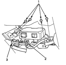
- 1. TORX BOLTS
- 2. MAIN WIRE HARNESS 8P CONNECTOR
- 3. SRS MAIN HARNESS 18P CONNECTOR
Installation
- 1.
Install the new SRS unit with Torx bolts, then connect the SRS main harness 18P and main wire harness 8P connectors to the SRS unit; push it into position until it clicks.
NOTE: When tightening the Torx bolts to the specified torque after replacement, be careful to turn them in so that their heads rest squarely on the brackets.
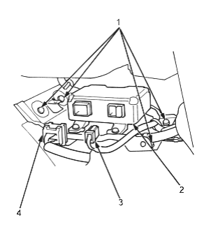
- 1. TORX BOLTS 9.8 Nm (1.0 kgf/m, 7.2 lbf/ft) Use a Torx T30 bit
- 2. SRS UNIT
- 3. MAIN WIRE HARNESS 8P CONNECTOR
- 4. SRS MAIN HARNESS 18P CONNECTOR
- 2.Install the SRS unit cover.
- 3.Install the console assembly (see section 20).
- 4.Reconnect the airbag and seat belt tensioner connectors (See Page 24-23).
- 5.Reconnect the negative battery cable.
- 6.After installing the SRS unit, confirm proper system operation. Turn the ignition switch ON (II); the SRS indicator light should come on for about six seconds then go off.