PDF p. 1336 · 24-66
Removal
- 1.Make sure the wheels are aligned straight ahead.
- 2.Disconnect the negative battery cable and wait at least three minutes.
- 3.Remove the driver’s airbag (See Page 24-60).
- 4.Disconnect the connector from the mode select switch, then remove the steering wheel bolt.
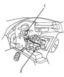
- 1. STEERING WHEEL BOLT
- 2. MODE SELECT SWITCH CONNECTOR
- 5.Align the front wheels straight ahead, then remove the steering wheel with a steering wheel puller. Do not tap on the steering wheel or steering column shaft when removing the steering wheel.
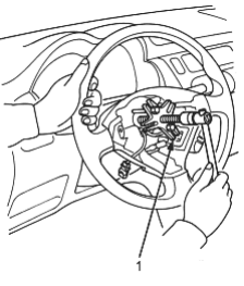
- 1. STEERING WHEEL PULLER
- 6.Remove the column covers.
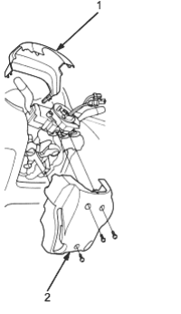
- 1. UPPER COLUMN COVER
- 2. LOWER COLUMN COVER
- 7.Disconnect the SRS main harness 2P connector from the cable reel 2P connector, then disconnect the main wire harness 4P (3P) connector from the horn/mode select switch connector.
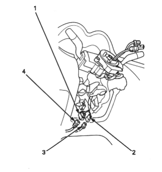
- 1. CABLE REEL 2P CONNECTOR
- 2. HORN/MODE SELECT SWITCH CONNECTOR
- 3. MAIN WIRE HARNESS 4P (3P) CONNECTOR
- 4. SRS MAIN HARNESS 2P CONNECTOR
PDF p. 1337 · 24-67
- 8.Remove the screw from the cable reel, then remove the cable reel from the column.
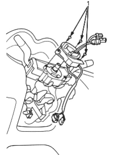
- 1. SCREWS
Installation
- 1.Before installing the steering wheel, the front wheels should be aligned straight ahead.
- 2.Be sure to check the negative cable from the battery is disconnected.
- 3.Set the cancel sleeve so that the projections are aligned vertically.
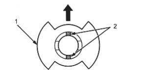
- 1. CANCEL SLEEVE
- 2. PROJECTIONS
- 4.Carefully install the cable reel on the steering column shaft. Then connect the 4P (3P) connector to the horn/mode select switch connector and connect the 2P connector to the SRS main harness.
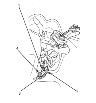
- 1. CABLE REEL 2P CONNECTOR
- 2. HORN/MODE SELECT SWITCH CONNECTOR
- 3. MAIN WIRE HARNESS 4P (3P) CONNECTOR
- 4. SRS MAIN HARNESS 2P CONNECTOR
PDF p. 1338 · 24-68
- 5.Install the steering column covers.
- 6.If necessary, centre the cable reel. (New replacement cable reels come centred.) Do this by first rotating the cable reel clockwise until it stops. Then rotate it counterclockwise (approximately two and a half turns) until the arrow mark on the cable reel label points straight up.
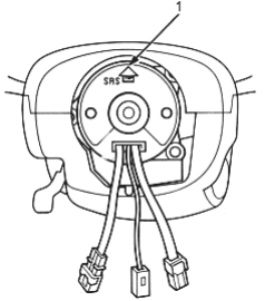
- 1. ARROW MARK
- 7.Align the projections on the cable reel with the holes on the steering wheel and install the steering wheel with a new steering wheel bolt.
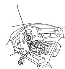
- 1. STEERING WHEEL BOLT, 38 Nm (3.9 kgf/m, 28 lbf/ft)
- 8.Install the driver’s airbag (See Page 24-61).
- 9.Reconnect the negative battery cable.
- 10.After installing the cable reel, confirm proper system operation:
- Turn the ignition switch ON (II); the SRS indicator light should come on for about six seconds and then go off.
- After the SRS indicator light has gone off, turn the steering wheel fully left and right to confirm the SRS indicator light does not come on.
- Make sure the horn button works.