PDF p. 1340 · 24-70
Procedure
Before scrapping any deployment units (airbags or seat belt tensioners) (including those in a whole vehicle to be scrapped), the deployment units must be deployed. If the vehicle is still within the warranty period, before you deploy the deployment units, the local Honda Service Manager must give approval and/or special instructions. Only after the deployment units (as a result of vehicle collision, for example), can they be scrapped. If the deployment units appear intact (not deployed or triggered) treat them with extreme caution.
Follow this procedure:
- 1.Deployment Preparations (See Page 24-71).
- 2.Deployment (See Page 24-75) and (See Page 24-76).
- 3.Disposal (See Page 24-76).
Deployment Tool Check
- 1.Connect the yellow clips to both switch protector handles on the tool and connect the red (+) and black (-) clips to a 12V battery.
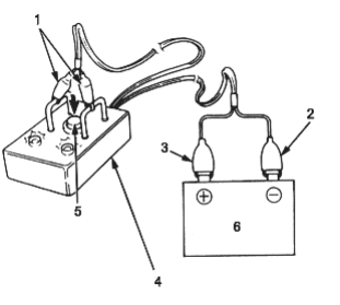
- 1. YELLOW CLIPS
- 2. BLACK CLIP
- 3. RED CLIP
- 4. DEPLOYMENT TOOL, 07HAZ-SG00500
- 5. OPERATION SWITCH
- 6. 12V BATTERY
- 2.Push the operation switch; green means the tool is OK, red means the tool is faulty.
- 3.After the check, disconnect the red and black clips from the battery and connect them to each other.
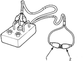
- 1. RED CLIP
- 2. BLACK CLIP
PDF p. 1341 · 24-71
In-vehicle Deployment Preparations
NOTE: If an SRS vehicle is to be entirely scrapped, its deployment units should be deployed while still in the vehicle. The deployment units should not be considered as salvageable parts and should never be installed in another vehicle.
Necessary equipment:
- Deployment tool
- Fully charged 12 volt battery
Without deployment tool
- Fully charged 12 volt battery
- 12 to 15 m (40 to 50 ft) of vinyl double cable
- Insulation tape
- 1.Disconnect the negative battery cable and wait for at least three minutes.
- 2.With Deployment Tool: Confirm that the deployment tool is functioning properly by following the check procedure on the tool box label (See Page 24-70).
- 3.Without Deployment Tool: Strip both ends of the vinyl double cable about 15 mm (0.60 in) and intertwine the wires on one end.
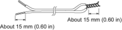
Driver’s Airbag
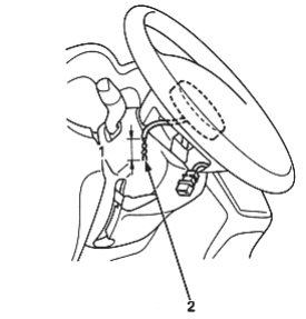
- 4.Disconnect the driver’s airbag 2P connector from the cable reel (See Page 24-31).
Front Passenger’s Airbag
- 5.Disconnect the front passenger’s airbag 2P connector from the SRS main harness (See Page 24-32).
Seat Belt Tensioner:
- 6.Disconnect the seat belt tensioner 2P connector from the SRS main harness (See Page 24-32).
- 7.Pull the seat belt out all the way and cut it.
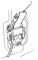
- 1. CUT
- 8.Cut off the airbag or seat belt tensioner connector, and strip the ends of the airbag wires about 15 mm (0.60 in) and twist them together.
Example
- 1. About 15 mm (0.60 in)
- 2. Twist
PDF p. 1342 · 24-72
- 9.With Deployment Tool: Connect the deployment tool alligator clips to the deployment wires as shown. Place the deployment tool at least 10 metres (thirty feet) away from the airbag.
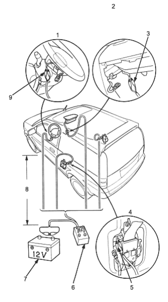
- 1. DRIVER’S AIRBAG
- 2. FRONT PASSENGER’S AIRBAG
- 3. ALLIGATOR CLIPS (Yellow)
- 4. SEAT BELT TENSIONER
- 5. ALLIGATOR CLIPS (Yellow)
- 6. DEPLOYMENT TOOL, 07HAZ-SG00500
- 7. BATTERY
- 8. At least 10 metres (thirty feet)
- 9. ALLIGATOR CLIPS (Yellow)
- 10.Without Deployment Tool: Connect the wires of the vinyl double cable which were not intertwined in step 8 to the deployment unit wires as shown and put insulation tape over the connections. Place the battery at least 10 metres (thirty feet) away from the vehicle.
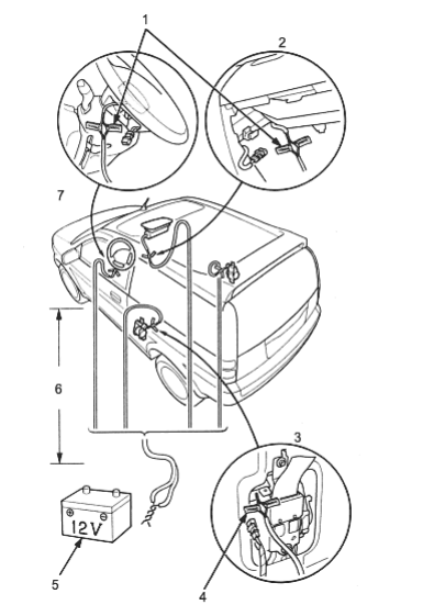
- 1. INTERTWINED WIRES
- 2. FRONT PASSENGER’S AIRBAG
- 3. SEAT BELT TENSIONER
- 4. INTERTWINED WIRES
- 5. BATTERY
- 6. At least 10 metres (thirty feet)
- 7. DRIVER’S AIRBAG
- 11.With Deployment Tool (See Page 24-75).
- 12.Without Deployment Tool (See Page 24-76).
PDF p. 1343 · 24-73
Out-of-vehicle Deployment Preparations
NOTE: If an intact airbag or seat belt tensioner has been removed from a scrapped vehicle or has been found defective or damaged during transit, storage or service, it should be deployed as follows:
Necessary equipment:
- Deployment tool
Without deployment tool
- 12 to 15 m (40 to 50 ft) of vinyl double cable
- Insulation tape
Other
- Fully charged 12 volt battery
Four tyres for 15 inch wheels or bigger without wheel and one tyre of the same size with wheel.
NOTE:
- Preferably used tyres.
- Tyres which were used for airbag deployment can be reused on vehicles after carefully cleaning their inner side with water.
- Vehicle wire harness with a core wire cross sectional area of at least 1.25 mm 2 (0.002 in2) or iron wire with a diameter of more than 1.2 mm (0.05 in).
- 1.Turn the ignition switch OFF. Disconnect the negative battery cable and wait for at least three minutes.
- 2.With Deployment Tool: Confirm that the deployment tool is functioning properly by following the check procedure on the tool box label (See Page 24-70).
- 3.Without Deployment Tool: Strip both ends of the vinyl double cable about 15 mm (0.60 in) and intertwine the wires on one end.
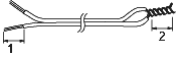
- 1. About 15 mm (0.60 in)
- 2. About 15 mm (0.60 in)
- 4.Remove the driver’s airbag (See Page 24-60).
- 5.Remove the front passenger’s airbag (See Page 24-62).
- 6.Remove the seat belt tensioner (See Page 24-64).
- 7.With vehicle wire harness or wire, tie two of the wheel-less tyres together, then tie one wheel-less tyre and the wheel-installed tyre together. (Wind around at least two times.)
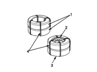
- 1. WHEEL-LESS TYRES
- 2. WHEEL INSTALLED TYRE
- 3. WHEEL-LESS TYRE
- 4. WIRE HARNESS or WIRE Wind around at least two times
- 8.Tie the airbag or the seat belt tensioner with vehicle wire harness or wire to the remaining wheel-less tyre as shown. (Wind around three times.)
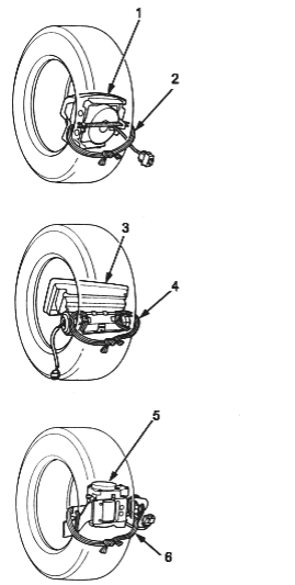
- 1. DRIVER’S AIRBAG
- 2. WIRE HARNESS or WIRE
Wind around three times - 3. FRONT PASSENGER’S AIRBAG
- 4. WIRE HARNESS or WIRE
Wind around three times - 5. SEAT BELT TENSIONER
- 6. WIRE HARNESS or WIRE
Wind around three times
PDF p. 1345 · 24-74
- 9.Place the set of two wheel-less tyres on flat ground and place the tyre with the airbag or sea belt tensioner on them.
- 10.Cut off the airbag or seat belt tensioner connector, strip the ends of the airbag or seat belt tensioner wires about 15 mm (0.60 in) and twist them together.
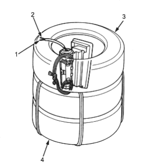
- 1. About 15 mm (0.60 in)
- 2. Twist
- 3. TYRE with installed AIRBAG OR SIDE AIRBAG OR SEATBELT TENSIONER
- 4. WHEEL-LESS TYRE SET
- 11.With Deployment Tool: Connect the deployment tool alligator clips to the airbag or seat belt tensioner wires.
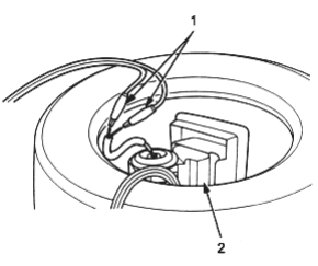
- 1. ALLIGATOR CLIPS (Yellow)
- 2. INFLATOR BODY
- 12.Without Deployment Tool: Connect the wires of the vinyl double cable which were not intertwined in step 3 to the airbag or seat belt tensioner wires as shown and put insulation tape over the connections.
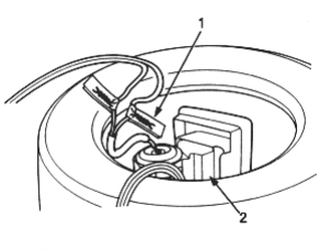
- 1. INSULATION TAPE
- 2. INFLATOR BODY
- 13.With Deployment Tool: With the wheel-installed tyre up, put the second pair of tyres on top of the other three tyres and tie the upper and lower tyre sets together. Place the deployment tool at lest 10 metres (thirty feet) away from the tyres.
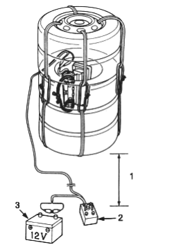
- 1. At least 10 metres (thirty feet)
- 2. DEPLOYMENT TOOL, 07HAZ-SG00500
- 3. BATTERY
PDF p. 1346 · 24-75
- 14.Without Deployment Tool: With the wheel-installed tyre up, put the second pair of tyres on top of the other three tyres and tie the upper and lower tyre sets together. Place the deployment tool at lest 10 metres (thirty feet) away from the tyres.
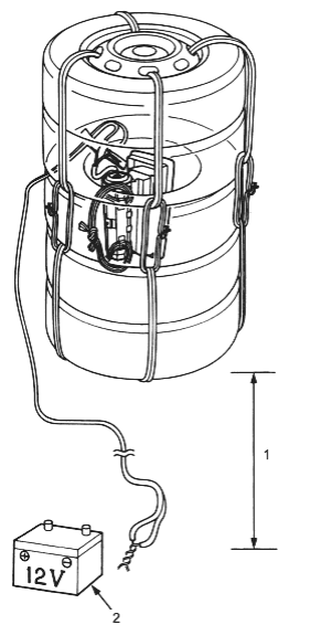
- 1. At least 10 metres (thirty feet)
- 2. BATTERY
- 15.With Deployment Tool (See Page 24-75).
- 16.Without Deployment Tool (See Page 24-76).
Deployment (With Deployment Tool)
- 1.Connect the red (+) and black (-) clips of the deployment tool to the 12V battery.
- If the green light on the tool comes on, the airbag igniter circuit is defective and cannot deploy the airbag. In this case refer to Damaged Airbag, Seat Belt Tensioner Special Procedure under Disposal (See Page 24-76).
- If the red light on the tool comes on, the airbag is ready to be deployed.
- 2.Push the tool’s operation switch. The airbag should deploy (deployment is both highly audible and visible; a loud noise and rapid inflation of the bag followed by slow deflation).
- If audible/visible deployment happens and the green light on the tool comes on go to Disposal (See Page 24-76).
- If the airbag does not deploy, yet the green light comes on, the igniter is defective. Go to Damaged Airbag, Seat Belt Tensioner Special Procedure under Disposal (See Page 24-76).
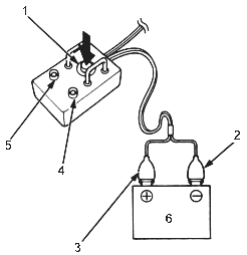
- 1. OPERATION SWITCH
- 2. BLACK CLIP
- 3. RED CLIP
- 4. RED LIGHT
- 5. GREEN LIGHT
- 6. 12V BATTERY
PDF p. 1347 · 24-76
Deployment (Without Deployment Tool)
Untwist the stripped ends of the vinyl double cable and connect them to the 12 volt battery. The deployment unit should deploy (deployment is both highly audible and visible; a loud noise and rapid inflation of the bag followed by slow deflation).
- If audible/visible deployment happens and the green light on the tool comes on go to Disposal (See Page 24-76).
- If the airbag does not deploy, yet the green light comes on, the igniter is defective. Go to Damaged Airbag, Seat Belt Tensioner Special Procedure under Disposal ( See Page 24-76).
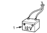
- 1. BATTERY
Disposal
In accordance with local regulations, dispose of the complete deployment unit. No part of it can be reused. Place it in a sturdy plastic bad and seal it securely.
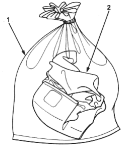
- 1. STURDY PLASTIC BAG
- 2. AIRBAG
Damaged Airbag, Seat Belt Tensioner Special Procedure
- 1.If installed in a vehicle, follow the removal procedure (See Page 24-60).
- 2.Intertwine the stripped ends of the two deployment unit wires to make a short circuit.
- 3.Package the deployment unit in exactly the same packaging that the new replacement part came in.
- 4.Mark the outside of the box “DAMAGED AIRBAG NOT DEPLOYED” so it does not get confused with your parts stock.
- 5.Contact your local Honda Service Manager for how and where to return it for disposal.