PDF p. 1287 · 24-24
Self-diagnostic Precautions
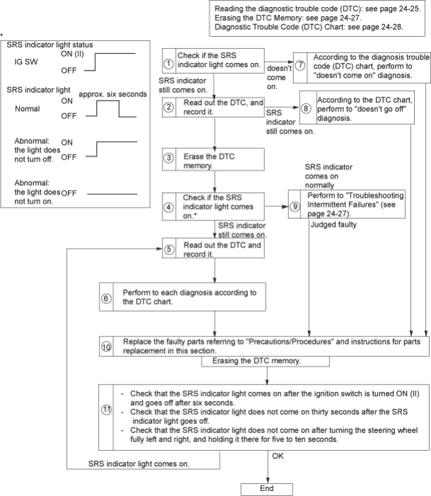
For correct and effective troubleshooting, follow the flowchart below.
NOTE:
- Observe the precautions and the procedure described in this section in performing troubleshooting.
- Make sure the battery is sufficiently charged. If the battery is dead or low, measuring value won’t be correct.
- When performing diagnosis for an open or damage in the wire harness, check the condition of the connectors and visually inspect the terminals for corrosion, bent pins or other damage.
PDF p. 1288 · 24-25
Reading the DTC (Diagnostic Trouble Code)
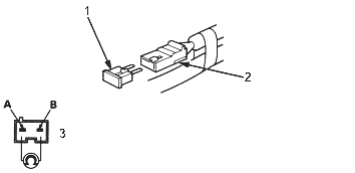
The SRS indicator light indicates the DTC by the number of blinks when the SCS short connector is connected to the service check connector (2P).
- 1.Turn the ignition switch OFF, and wait for ten seconds. Then connect the SCS short connector to the service check connector (2P). If you don’t wait ten seconds, the SRS unit won’t be completely reset or outputs DTCs.
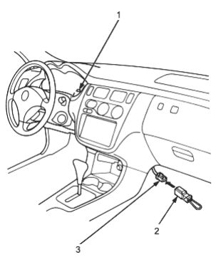
- 1. SRS INDICATOR LIGHT
- 2. SCS SHORT CONNECTOR, 07PAZ-0010100
- 3. SERVICE CHECK CONNECTOR (2P), [BRN/BLK, BRN]
- 2.Turn the ignition switch ON (II). The SRS indicator light comes on for about six seconds and then goes off. Then it will indicate the DTC.
- 3.Read the DTC.
- 4.Turn the ignition switch OFF, and wait for ten seconds. Then disconnect the SCS short connector from the service check connector (2P).
Patterns of the DTC Indications:
The DTC consists of a main code and sub-code.
S: Second
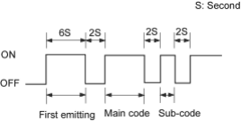
Reading the main code:
Count the number of blinks.
Example:
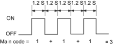
Reading the sub code:
Count the number of blinks.
Example
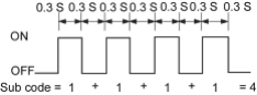
In case of main code is ‘3’, sub code is ‘4’, record DTC3-4.
PDF p. 1289 · 24-26
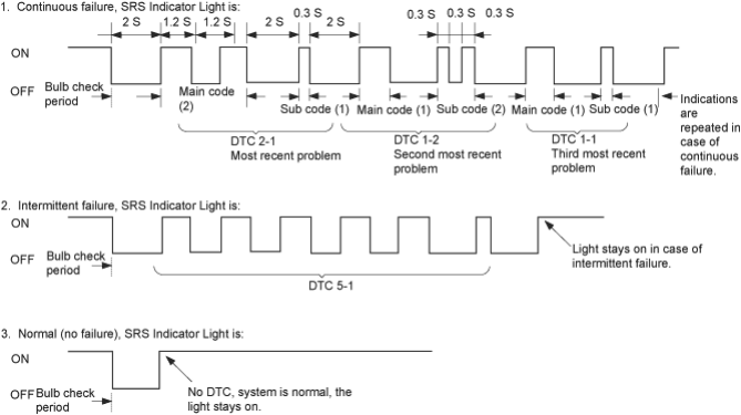
- Including the most recent problem, up to three different malfunctions can be indicated (see example 1 below).
- In case of a continuous failure, the DTC will be indicated repeatedly (see example 1 below).
- In case of an intermittent failure, the SRS indicator light will indicate the DTC one time, then it will stay on (see example 2 below).
- If both a continuous and an intermittent failure occurs, both DTCs will be indicated as continuous failures.
- When the system is normal (no DTC), the SRS indicator light will stay on (see example 3).
- If the SRS indicator light comes on continually without DTC, it will be faulty.
Examples of the DTC Indications:
PDF p. 1290 · 24-27
Erasing the DTC Memory
To erase the DTC(s) from the SRS unit, use a Honda PGM Tester SRS vehicle System Supplement or the following procedure.
- 1.Make sure the ignition switch is OFF.
- 2.Connect the SCS short connector to the MES connector (2P). Do not use a jumper wire.
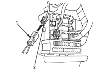
- 1. SCS SHORT CONNECTOR, 07PAZ-0010100
- 2. MEMORY ERASE SIGNAL (MES) CONNECTOR (2P) [GRN, GRN] or [BLK, LT GRN/BLK]
- 3.Turn the ignition switch ON (II).
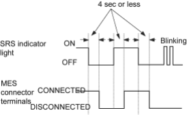
- 4.The SRS indicator light comes on for about six seconds and goes off. Remove the SCS short connector from the MES connector (2P) within four seconds after the SRS indicator goes off.
- 5.The SRS indicator light comes on again. Reconnect the SCS short connector to the MES connector (2P) within four seconds.
- 6.The SRS indicator light goes off. Remove the SCS short connector from the MES connector (2P) within four seconds.
- 7.The SRS indicator light indicates that the memory is erased by blinking two times.
- 8.Turn the ignition switch OFF and wait for ten seconds.
Troubleshooting Intermittent Failures
If there was a malfunction, but it doesn’t recur, it will be stored in the memory as an intermittent failure and the SRS indicator light comes on.
After checking the DTC, troubleshoot as follows:
- 1.Read the DTC (see Reading the DTC).
- 2.Erase the DTC memory (see “Erasing the DTC Memory”).
- 3.With the shift lever in neutral, start the engine and let the engine idle.
- 4.The SRS indicator light goes on for about six seconds and then goes off.
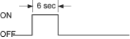
- 5.Shake the wire harness and connector, take a test drive (quick acceleration, quick braking, cornering), and turn the steering wheel fully left and right, and hold it there for five to ten seconds. If the problem recurs, the SRS indicator light will stay on.
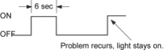
- 6.If you can’t duplicate the intermittent failure, the system is OK at this time.
PDF p. 1291 · 24-28
Diagnostic Trouble Code (DTC) Chart
| SRS indicator | DTC | Possible cause | Corrective action | See page |
|---|---|---|---|---|
| light | ||||
| doesn’t come on | none | Faulty SRS indicator light circuit | Troubleshooting | (See Page |
| (doesn’t | 24-33) | |||
| come on) | ||||
| comes on | none | Faulty SRS indicator light circuit, internal | Troubleshooting | (See Page |
| (doesn’t go | failure of SRS unit, faulty SRS power supply | 24-36) | ||
| off) | (VB line) | |||
| comes on | 1-1 | Open or increased resistance in the driver’s | Troubleshooting | (See Page |
| airbag | 24-40) | |||
| comes on | 1-2 | Increased resistance in the driver’s airbag | Troubleshooting | (See Page |
| inflator | 24-40) | |||
| comes on | 1-3 | Short to another wire or decreased | Troubleshooting | (See Page |
| resistance in the driver’s airbag inflator | 24-41) | |||
| comes on | 1-4 | Short to power in the driver’s airbag inflator | Troubleshooting | (See Page |
| 24-42) | ||||
| comes on | 1-5 | Short to ground in the driver’s airbag inflator | Troubleshooting | (See Page |
| 24-43) | ||||
| comes on | 2-1 | With front passenger’s airbag: | Troubleshooting | (See Page |
| Open in the front passenger’s airbag inflator | 24-44) | |||
| Without front passenger’s airbag: | Troubleshooting | (See Page | ||
| Open in the dummy resistor | 24-48) | |||
| comes on | 2-2 | With front passenger’s airbag: | Troubleshooting | (See Page |
| Increased resistance in the front | 24-44) | |||
| passenger’s airbag inflator | ||||
| Without front passenger’s airbag: | Troubleshooting | (See Page | ||
| Increased resistance in the dummy resistor | 24-48) | |||
| comes on | 2-3 | With front passenger’s airbag: | Troubleshooting | (See Page |
| Short to another wire or decreased | 24-45) | |||
| resistance in the passenger’s airbag inflator | ||||
| Without front passenger’s airbag: | Troubleshooting | (See Page | ||
| Short to another wire or decreased | 24-49) | |||
| resistance in the dummy resistor | ||||
| comes on | 2-4 | With front passenger’s airbag: | Troubleshooting | (See Page |
| Short to power in the front passenger’s | 24-46) | |||
| airbag inflator | ||||
| Without front passenger’s airbag: | Troubleshooting | (See Page | ||
| Short to power in the dummy resistor | 24-50) | |||
| comes on | 2-5 | With front passenger’s airbag: | Troubleshooting | (See Page |
| Short to ground in the front passenger’s | 24-47) | |||
| airbag inflator | ||||
| Without front passenger’s airbag: | Troubleshooting | (See Page | ||
| Short to power in the dummy resistor | 24-51) |
PDF p. 1292 · 24-29
| SRS indicator | DTC | Possible cause | Corrective action | See page |
|---|---|---|---|---|
| light | ||||
| comes on | 3-1 | Open in the left side seat belt tensioner | Troubleshooting | (See Page |
| 24-52) | ||||
| comes on | 3-2 | Increased resistance in the left side seat | Troubleshooting | (See Page |
| belt tensioner | 24-52) | |||
| comes on | 3-3 | Short to another wire or decreased | Troubleshooting | (See Page |
| resistance in the left side seat belt tensioner | 24-53) | |||
| comes on | 3-4 | Short to power in the left side seat belt | Troubleshooting | (See Page |
| tensioner | 24-54) | |||
| comes on | 3-5 | Short to ground in the left side seat belt | Troubleshooting | (See Page |
| tensioner | 24-55) | |||
| comes on | 4-1 | Open in the right side seat belt tensioner | Troubleshooting | (See Page |
| 24-56) | ||||
| comes on | 4-2 | Increased resistance in the right side seat | Troubleshooting | (See Page |
| belt tensioner | 24-56) | |||
| comes on | 4-3 | Short to another wire or decreased | Troubleshooting | (See Page |
| resistance in the right side seat belt | 24-57) | |||
| tensioner | ||||
| comes on | 4-4 | Short to power in the right side seat belt | Troubleshooting | (See Page |
| tensioner | 24-58) | |||
| comes on | 4-5 | Short to ground in the right side seat belt | Troubleshooting | (See Page |
| tensioner | 24-59) | |||
| comes on | 5-2 | Internal failure of the SRS unit | SRS unit | (See Page |
| replacement | 24-69) | |||
| comes on | 5-4 | Internal failure of the SRS unit | SRS unit | (See Page |
| replacement | 24-69) | |||
| comes on | 6-4 | Internal failure of the SRS unit | SRS unit | (See Page |
| replacement | 24-69) | |||
| comes on | 7-1 | Internal failure of the SRS unit | SRS unit | (See Page |
| replacement | 24-69) | |||
| comes on | 7-2 | Internal failure of the SRS unit | SRS unit | (See Page |
| replacement | 24-69) | |||
| comes on | 7-3 | Internal failure of the SRS unit | SRS unit | (See Page |
| replacement | 24-69) | |||
| comes on | 8-1 | Internal failure of the SRS unit | SRS unit | (See Page |
| replacement | 24-69) | |||
| comes on | 8-2 | Internal failure of the SRS unit | SRS unit | (See Page |
| replacement | 24-69) | |||
| comes on | 8-3 | Internal failure of the SRS unit | SRS unit | (See Page |
| replacement | 24-69) | |||
| comes on | 8-4 | Internal failure of the SRS unit | SRS unit | (See Page |
| replacement | 24-69) | |||
| comes on | 8-5 | Internal failure of the SRS unit | SRS unit | (See Page |
| replacement | 24-69) | |||
| comes on | 8-6 | Internal failure of the SRS unit | SRS unit | (See Page |
| replacement | 24-69) | |||
| comes on | 9-1 *1 | Internal failure of the SRS unit | SRS unit | (See Page |
| replacement | 24-69) | |||
| comes on | 9-2 *2 | Internal failure of the SRS unit | SRS unit | (See Page |
| replacement | 24-69) | |||
| comes on | 10-1 | SRS airbags deployed (SRS unit must be | SRS unit | (See Page |
| replaced) | replacement | 24-69) |
NOTE:
- *1:In case of an intermittent failure DTC 9-1, it means there was an internal failure of the SRS unit or a faulty SRS indicator light circuit. Do the troubleshooting for intermittent failures (See Page 24-27).
- *2:In case of an intermittent failure DTC 9-2, it means there was an internal failure of the power supply (VB line). Do the troubleshooting for intermittent failures (See Page 24-27).
PDF p. 1293 · 24-30
Fuse Box and Connector Locations
Fuse and Fo Connector:
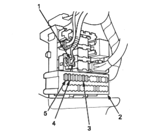
- 1. Fo CONNECTOR
- 2. UNDER-DASH FUSE/RELAY BOX
- 3. No. 6 (7.5A) FUSE
- 4. No. 2 (15A) FUSE
- 5. No. 1 (10A) FUSE
C1 Connector:
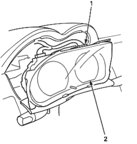
- 1. C1 CONNECTOR
- 2. GAUGE ASSEMBLY
C2, C3, C4 and C5 Connector:
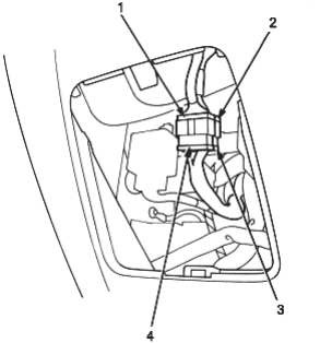
- 1. C2 CONNECTOR
- 2. C4 CONNECTOR
- 3. C5 CONNECTOR
- 4. C3 CONNECTOR
U1o and U2o Connector:
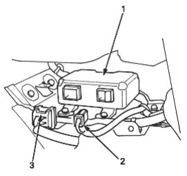
- 1. SRS UNIT
- 2. U2o CONNECTOR
- 3. U1o CONNECTOR
PDF p. 1295 · 24-31
D1o Connector and D1i Connector:
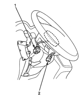
- 1. D1o CONNECTOR
- 2. D1i CONNECTOR
Connecting the special tool to the D1i connector:
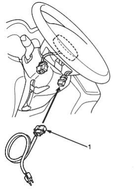
- 1. SRS SIMULATOR LEAD C, 07TAZ-SZ5011A and SRS INFLATOR SIMULATOR (2 OHM JACK), 07SAZ-TB4011A
D2o and D2i connector:
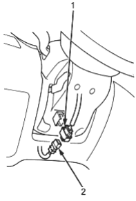
- 1. D2o CONNECTOR
- 2. D2i CONNECTOR
Connecting the special tool to the D2i connector:
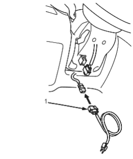
- 1. SRS SIMULATOR LEAD C, 07TAZ-SZ5011A and SRS INFLATOR SIMULATOR (2 OHM JACK), 07SAZ-TB4011A
PDF p. 1296 · 24-32
P1o and P1i connector:
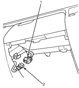
- 1. P1o CONNECTOR
- 2. P1i CONNECTOR
Connecting the special tool to the P1i Connector:
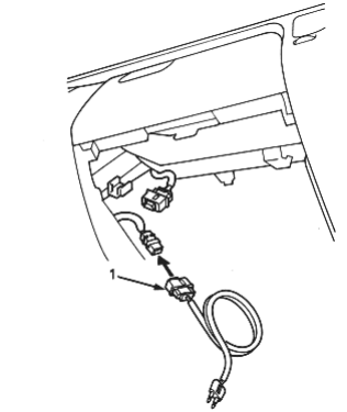
- 1. SRS SIMULATOR LEAD C, 07TAZ-SZ5011A and SRS INFLATOR SIMULATOR (2 OHM JACK), 07SAZ-TB4011A
TL1i Connector and TL1i Connector (left side) or TR1o Connector and TR1i Connector (right side)|:
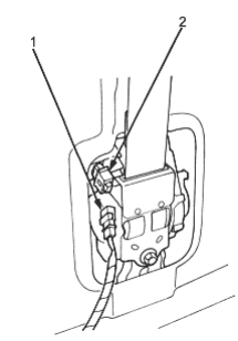
- 1. TL1i (TR1i) CONNECTOR
- 2. TL1o (TR1o) CONNECTOR
Connecting the special tool to the TL1i (or TR1i) Connector:
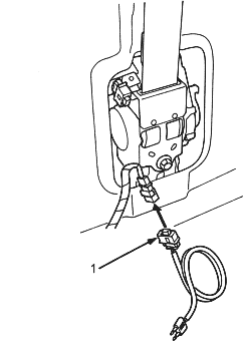
- 1. SRS SIMULATOR LEAD C, 07TAZ-SZ5011A and SRS INFLATOR SIMULATOR (2 OHM JACK), 07SAZ-TB4011A
PDF p. 1297 · 24-33
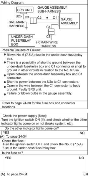
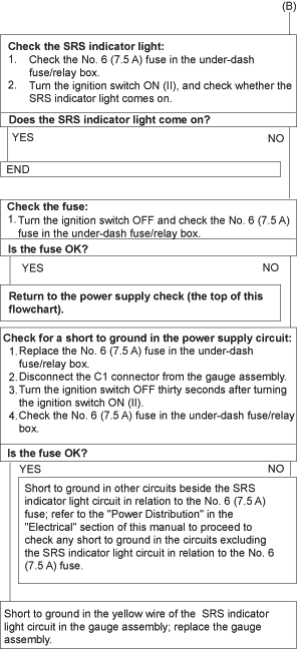
The SRS Indicator Light Doesn’t Come On
PDF p. 1298 · 24-34
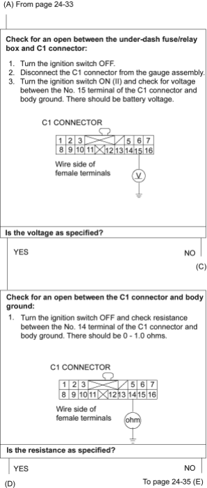
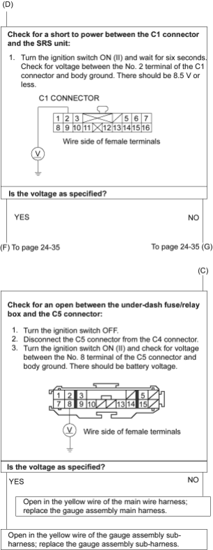
PDF p. 1299 · 24-35
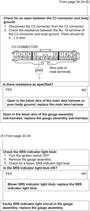
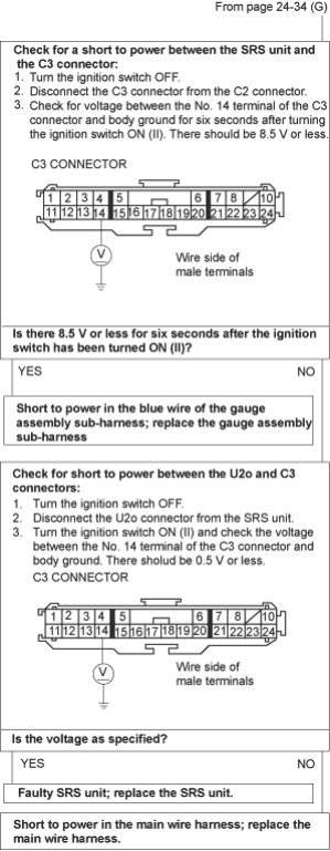
PDF p. 1300 · 24-36
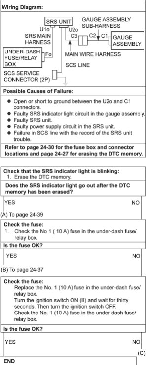
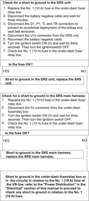
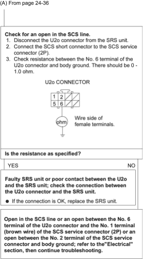
The SRS Indicator Light Doesn’t Go Off (During the DTC reading)
PDF p. 1301 · 24-37
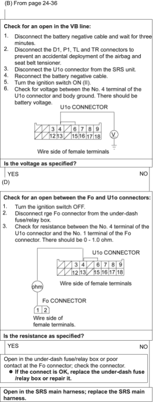
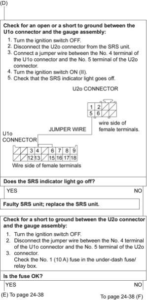
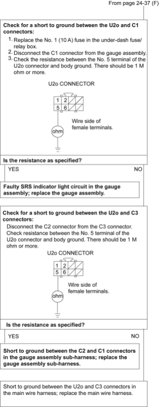
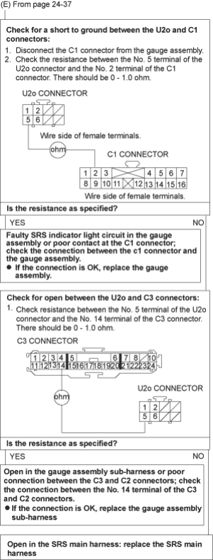
The SRS Indicator Light Doesn’t Go Off
PDF p. 1302 · 24-38
PDF p. 1303 · 24-39
PDF p. 1304 · 24-40
DTC 1-1 and DTC 1-2
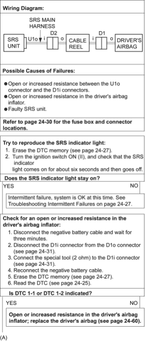
To go to the pages referenced on the diagram above, click on the following:
(See Page 24-30)
(See Page 24-27)
(See Page 24-31)
(See Page 24-25)
(See Page 24-60)
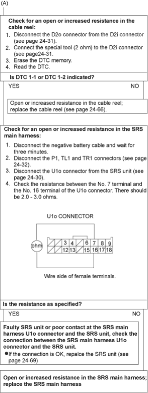
To go to the pages referenced on the diagram above,
click on the following:
(See Page 24-31) (See Page 24-66) (See Page 24-32) (See Page 24-30) (See Page 24-69)
PDF p. 1306 · 24-41
DTC 1-3
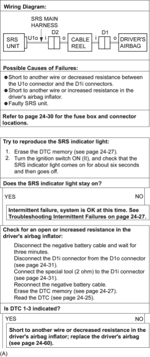
To go to the pages referenced on the diagram above, click on the following:
(See Page 24-30)
(See Page 24-27)
(See Page 24-31)
(See Page 24-25)
(See Page 24-60)
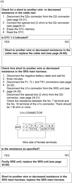
To go to the pages referenced on the diagram above,
click on the following:
(See Page 24-31) (See Page 24-66) (See Page 24-32) (See Page 24-30) (See Page 24-69)
PDF p. 1307 · 24-42
DTC 1-4
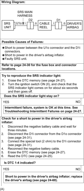
To go to the pages referenced on the diagram above, click on the following:
(See Page 24-30)
(See Page 24-27)
(See Page 24-31)
(See Page 24-25)
(See Page 24-60)
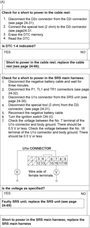
To go to the pages referenced on the diagram above,
click on the following:
(See Page 24-31) (See Page 24-66) (See Page 24-32) (See Page 24-30) (See Page 24-69)
PDF p. 1308 · 24-43
DTC 1-5
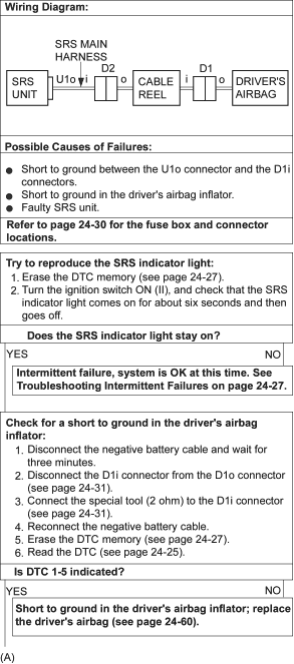
To go to the pages referenced on the diagram above, click on the following:
(See Page 24-30)
(See Page 24-27)
(See Page 24-31)
(See Page 24-25)
(See Page 24-60)
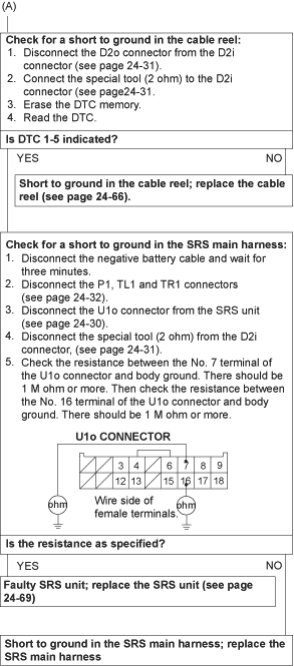
To go to the pages referenced on the diagram above,
click on the following:
(See Page 24-31) (See Page 24-66) (See Page 24-32) (See Page 24-30) (See Page 24-69)
PDF p. 1310 · 24-44
DTC 2-1 and DTC 2-2 (With front passenger’s airbag)
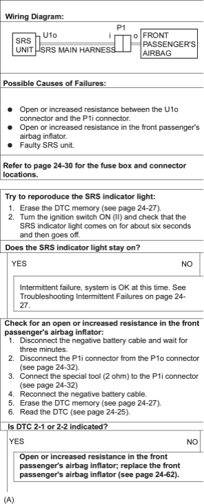
To go to the pages referenced on the diagram above, click on the following:
(See Page 24-30)
(See Page 24-27)
(See Page 24-31)
(See Page 24-25)
(See Page 24-60)
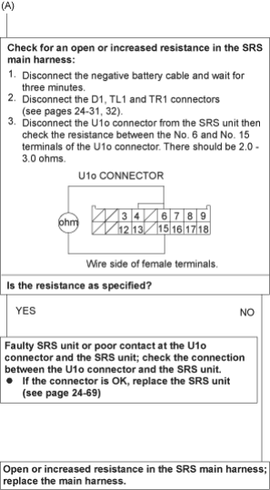
To go to the pages referenced on the diagram above,
click on the following:
(See Page 24-31) (See Page 24-32) (See Page 24-69)
PDF p. 1312 · 24-45
DTC 2-3 (With front passenger’s airbag)
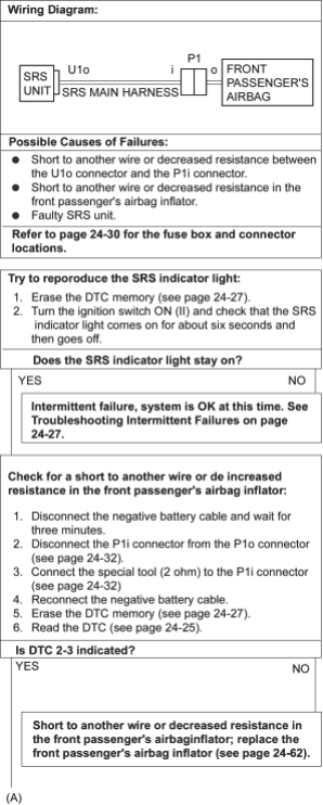
To go to the pages referenced on the diagram above, click on the following:
(See Page 24-30)
(See Page 24-27)
(See Page 24-32)
(See Page 24-25)
(See Page 24-62)
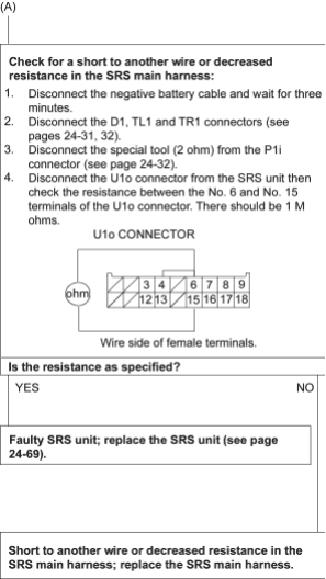
To go to the pages referenced on the diagram above,
click on the following:
(See Page 24-31) (See Page 24-32) (See Page 24-69)
PDF p. 1313 · 24-46
DTC 2-4 (With front passenger’s airbag)
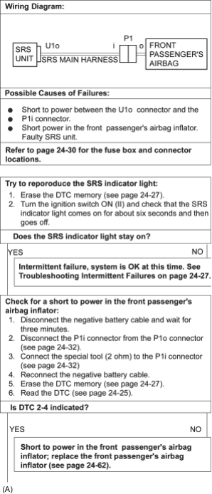
To go to the pages referenced on the diagram above, click on the following:
(See Page 24-30)
(See Page 24-27)
(See Page 24-32)
(See Page 24-25)
(See Page 24-62)
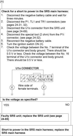
To go to the pages referenced on the diagram above,
click on the following:
(See Page 24-31) (See Page 24-32) (See Page 24-69)
PDF p. 1314 · 24-47
DTC 2-5 (With front passenger’s airbag)
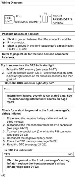
To go to the pages referenced on the diagram above, click on the following:
(See Page 24-30)
(See Page 24-27)
(See Page 24-32)
(See Page 24-25)
(See Page 24-62)
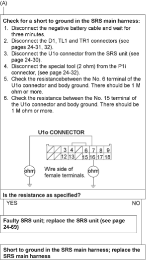
To go to the pages referenced on the diagram above,
click on the following:
(See Page 24-31) (See Page 24-32) (See Page 24-30) (See Page 24-69)
PDF p. 1315 · 24-48
DTC 2-1 and DTC 2-2 (Without front passenger’s airbag)
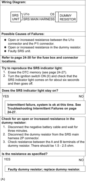
To go to the pages referenced on the diagram above, click on the following:
(See Page 24-30)
(See Page 24-27)
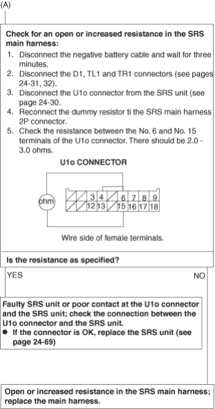
To go to the pages referenced on the diagram above,
click on the following:
(See Page 24-31) (See Page 24-32) (See Page 24-30) (See Page 24-69)
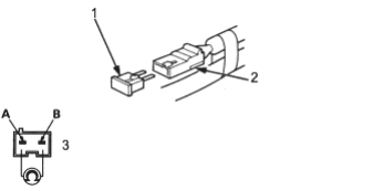
- 1. DUMMY RESISTOR
- 2. SRS MAIN HARNESS 2P CONNECTOR
- 3. DUMMY RESISTOR
PDF p. 1316 · 24-49
DTC 2-3 (Without front passenger’s airbag)
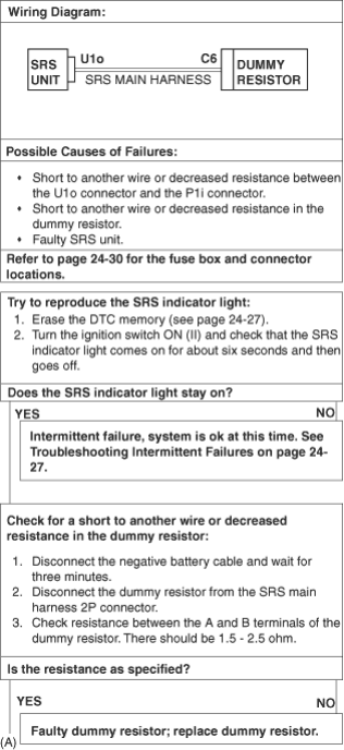
To go to the pages referenced on the diagram above, click
on the following:
(See Page 24-30) (See Page 24-27)
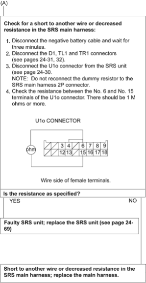
To go to the pages referenced on the diagram above,
click on the following:
(See Page 24-32) (See Page 24-30) (See Page 24-69)
- 1. DUMMY RESISTOR
- 2. SRS MAIN HARNESS 2P CONNECTOR
- 3. DUMMY RESISTOR
PDF p. 1317 · 24-50
DTC 2-4 (Without front passenger’s airbag)
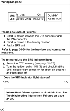
To go to the pages referenced on the diagram above, click on the following:
(See Page 24-30)
(See Page 24-27)
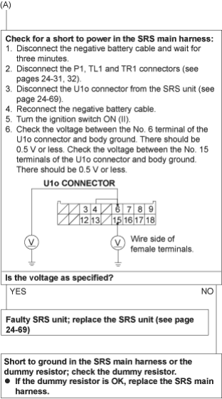
To go to the page referenced on the diagram above,
click on the following:
(See Page 24-69)
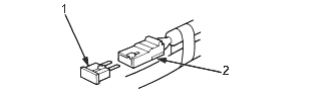
- 1. DUMMY RESISTOR
- 2. SRS MAIN HARNESS 2P CONNECTOR
PDF p. 1318 · 24-51
DTC 2-5 (Without front passenger’s airbag)
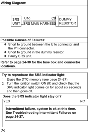
To go to the pages referenced on the diagram above, click on the following:
(See Page 24-30)
(See Page 24-27)
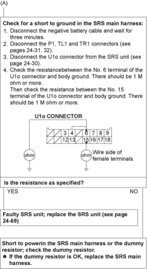
To go to the pages referenced on the diagram above,
click on the following:
(See Page 24-31) (See Page 24-32) (See Page 24-30) (See Page 24-69)
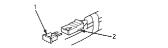
- 1. DUMMY RESISTOR
- 2. SRS MAIN HARNESS 2P CONNECTOR
PDF p. 1320 · 24-52
DTC 3-1 and DTC 3-2
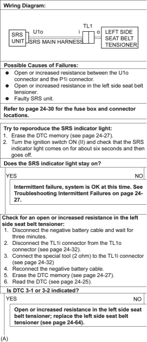
To go to the pages referenced on the diagram above, click on the following:
(See Page 24-30)
(See Page 24-27)
(See Page 24-32)
(See Page 24-25)
(See Page 24-64)
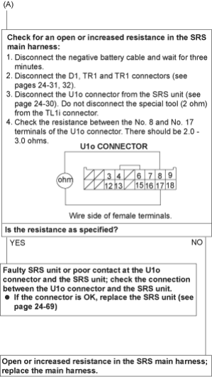
To go to the pages referenced on the diagram above,
click on the following:
(See Page 24-31) (See Page 24-32) (See Page 24-30) (See Page 24-69)
PDF p. 1321 · 24-53
DTC 3-3
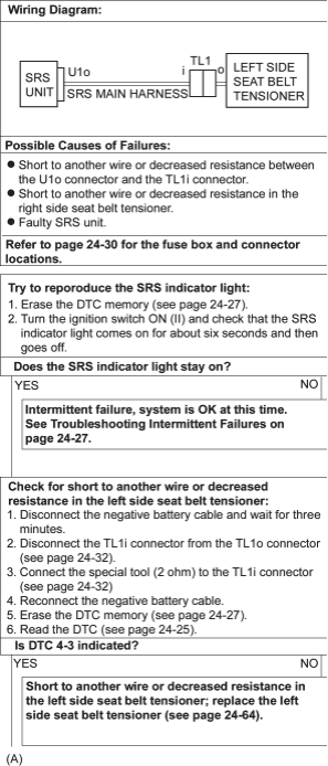
To go to the pages referenced on the diagram above, click on the following:
(See Page 24-30)
(See Page 24-27)
(See Page 24-32)
(See Page 24-25)
(See Page 24-64)
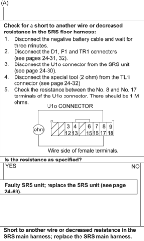
To go to the pages referenced on the diagram above,
click on the following:
(See Page 24-31) (See Page 24-32) (See Page 24-30) (See Page 24-69)
PDF p. 1322 · 24-54
DTC 3-4
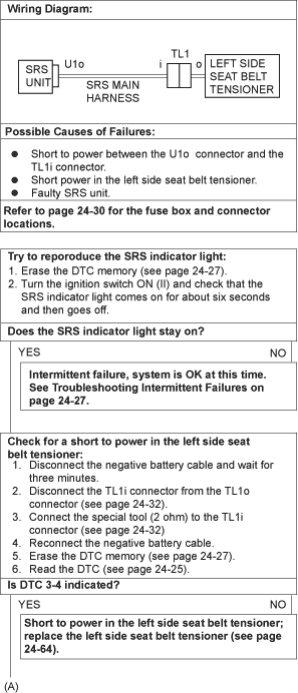
To go to the pages referenced on the diagram above, click on the following:
(See Page 24-30)
(See Page 24-27)
(See Page 24-32)
(See Page 24-25)
(See Page 24-64)
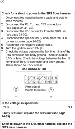
To go to the pages referenced on the diagram above,
click on the following:
(See Page 24-31) (See Page 24-32) (See Page 24-30) (See Page 24-69)
PDF p. 1324 · 24-55
DTC 3-5
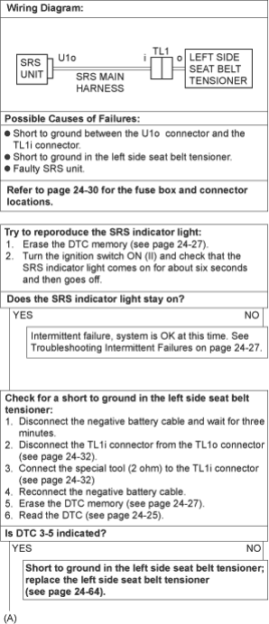
To go to the pages referenced on the diagram above, click on the following:
(See Page 24-30)
(See Page 24-27)
(See Page 24-32)
(See Page 24-25)
(See Page 24-64)
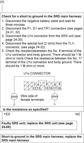
To go to the pages referenced on the diagram above,
click on the following:
(See Page 24-31) (See Page 24-32) (See Page 24-30) (See Page 24-69)
PDF p. 1325 · 24-56
DTC 4-1 and DTC 4-2
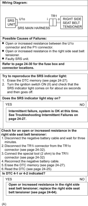
To go to the pages referenced on the diagram above, click on the following:
(See Page 24-30)
(See Page 24-27)
(See Page 24-32)
(See Page 24-25)
(See Page 24-64)
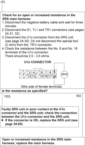
To go to the pages referenced on the diagram above,
click on the following:
(See Page 24-31) (See Page 24-32) (See Page 24-30) (See Page 24-69)
PDF p. 1326 · 24-57
DTC 4-3
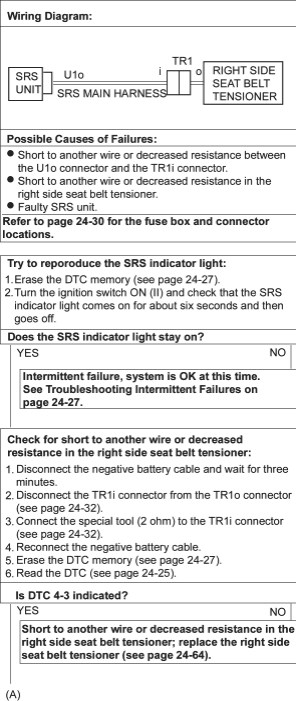
To go to the pages referenced on the diagram above, click on the following:
(See Page 24-30)
(See Page 24-27)
(See Page 24-32)
(See Page 24-25)
(See Page 24-64)
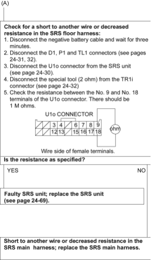
To go to the pages referenced on the diagram above,
click on the following:
(See Page 24-31) (See Page 24-32) (See Page 24-30) (See Page 24-69)
PDF p. 1327 · 24-58
DTC 4-4
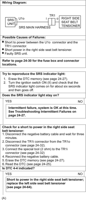
To go to the pages referenced on the diagram above, click on the following:
(See Page 24-30)
(See Page 24-27)
(See Page 24-32)
(See Page 24-25)
(See Page 24-64)
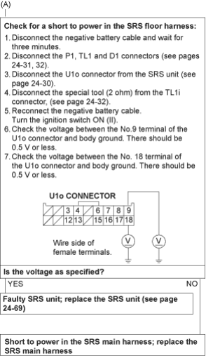
To go to the pages referenced on the diagram above,
click on the following:
(See Page 24-31) (See Page 24-32) (See Page 24-30) (See Page 24-69)
PDF p. 1328 · 24-59
DTC 4-5
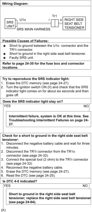
To go to the pages referenced on the diagram above, click on the following:
(See Page 24-30)
(See Page 24-27)
(See Page 24-32)
(See Page 24-25)
(See Page 24-64)
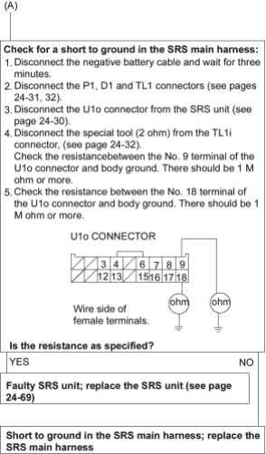
To go to the pages referenced on the diagram above,
click on the following:
(See Page 24-31) (See Page 24-32) (See Page 24-30) (See Page 24-69)