PDF p. 1204 · 23-E-10
NOTE: The control unit is built into the power window master switch and only controls driver’s door window operations.
- 1.Remove the power window master switch and armrest pocket from the door panel.
- 2.Disconnect the 14P connector from the power window master switch.
- 3.Inspect the connector and socket terminals to make sure they are all making good contact.
- If the terminals are bent, loose, or corroded, repair them as necessary and recheck the system.
- If the terminals look OK, make the following input tests at the connector.
- If any test indicates a problem, find and correct the cause, then recheck the system.
- If all the input tests prove OK, the control unit must be faulty, replace it.
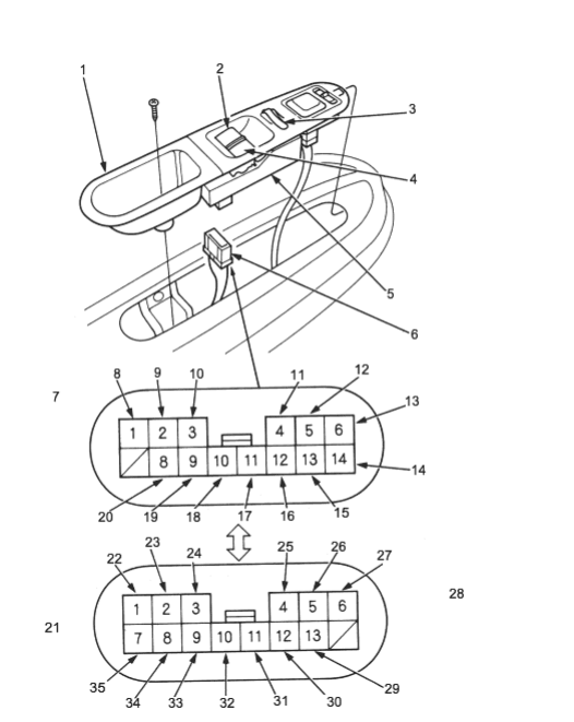
- 1. ARMREST POCKET
- 2. DRIVER’S SWITCH (LHD type) OR PASSENGER’S SWITCH (RHD type)
- 3. MAIN SWITCH
- 4. PASSENGER’S SWITCH (LHD type) OR DRIVER’S SWITCH (RHD type)
- 5. POWER WINDOW MASTER SWITCH
- 6. 14P CONNECTOR
- 7. LHD TYPE
- 8. BLK
- 9. BLK
- 10. RED/YEL
- 11. YEL/BLK
- 12. RED/BLU
- 13. BLU/ORN
- 14. GRN/BLK
- 15. BLU/YEL
- 16. BLK
- 17. BLU/BLK
- 18. WHT
- 19. BLU
- 20. YEL
- 21. RHD TYPE
- 22. BLU/YEL
- 23. RED/BLU
- 24. YEL/BLK
- 25. RED/YEL
- 26. BLK
- 27. BLK
- 28. Wire side of female terminals
- 29. YEL
- 30. BLU
- 31. WHT
- 32. BLU/BLK
- 33. BLK
- 34. BLU/ORN
- 35. GRN/BLK
PDF p. 1205 · 23-E-11
Disconnect the connector to the power window master switch
| Cavity | Wire | Test condition | Test: Desired result | Possible cause if result is | |
|---|---|---|---|---|---|
| not obtained | |||||
| 4 [3] | YEL/BLK | Ignition switch ON (II) | Check for voltage to ground: | ♦ | Blown No 51 (20A) fuse in |
| There should be battery voltage | the under-hood fuse/relay box. | ||||
| ♦ | Blown No. 4 (10A) fuse in | ||||
| the under-dash fuse/relay box | |||||
| ♦ | Faulty power window relay | ||||
| ♦ | Poor ground (G401, G402) | ||||
| ♦ | An open in the wire | ||||
| 14 [7] | GRN/BLK | Ignition switch ON (II) | Check for voltage to ground: | ♦ | Blown No 51 (20A) fuse in |
| There should be battery voltage | the under-hood fuse/relay box. | ||||
| ♦ | Blown No. 4 (10A) fuse in | ||||
| the under-dash fuse/relay box | |||||
| ♦ | Faulty power window relay | ||||
| ♦ | Poor ground (G401, G402) | ||||
| ♦ | An open in the wire | ||||
| 1 [6] | BLK | Under all conditions | Check for continuity to ground: | ♦ | Poor ground (G401, G402) |
| 12 [9] | There should be continuity | ♦ | An open in the wire | ||
| 13 [1] | BLU/YEL | Connect the No. 14 [7] | Check for passenger’s window | ♦ | Faulty passenger’s window |
| terminal to the No. 13 | motor: | motor | |||
| [1] terminal and the | It should run | ♦ | Faulty passenger’s window | ||
| No. 6 [8] terminal to | switch | ||||
| the No. 12 [9] terminal | ♦ | An open in the wire | |||
| then turn the ignition | |||||
| switch to ON (II). | |||||
| 6 [8] | BLU/ORN | Connect the No. 14 [7] | Check for passenger’s window | ♦ | Faulty passenger’s window |
| terminal to the No. 13 | motor: | motor | |||
| [1] terminal and the | It should run | ♦ | Faulty passenger’s window | ||
| No. 6 [8] terminal to | switch | ||||
| the No. 12 [9] terminal | ♦ | An open in the wire | |||
| then turn the ignition | |||||
| switch to ON (II). | |||||
| 11 [10] | BLU/BLK | Under all conditions | Check for voltage to ground: | ♦ | Blown No. 52 (20A) fuse in |
| There should be battery voltage | the under-hood fuse/relay box | ||||
| ♦ | An open in the wire | ||||
| 5 [2] | RED/BLU | Ignition switch ON (II) | Check the voltage between the | ♦ | Blown No. 4 (10A) fuse in |
| and the driver’s | No. 5 [2] and No. 1 [6] terminals: | the under-dash fuse/relay box | |||
| window switch | There should be battery voltage. | ♦ | Faulty power window master | ||
| MANUAL UP. | switch | ||||
| Ignition switch ON (II) | ♦ | An open in the wire | |||
| and the driver’s | |||||
| window switch AUTO | |||||
| UP | |||||
| 3 [4] | RED/YEL | Ignition switch ON (II) | Check the voltage between the | ♦ | Blown No. 4 (10A) fuse in |
| and the driver’s | No. 3 [4] and No. 1 [6] terminals: | the under-dash fuse/relay box | |||
| window switch | There should be battery voltage. | ♦ | Faulty power window master | ||
| MANUAL DOWN. | switch | ||||
| Ignition switch ON (II) | ♦ | An open in the wire | |||
| and the driver’s | |||||
| window switch AUTO | |||||
| DOWN | |||||
Reconnect the connector to the power window master switch.
| Cavity | Wire | Test condition | Test: Desired result | Possible cause if result is | |
|---|---|---|---|---|---|
| not obtained | |||||
| 10 [11] | WHT | Ignition switch ON (II) | Check for voltage to ground: | ♦ | Faulty power window master |
| There should be battery voltage | switch | ||||
| ♦ | An open in the wire | ||||
| 9 [12] | BLU | Ignition switch ON (II) | Check for voltage the No. 9 [12] | ♦ | Blown No 52 920A) fuse in |
| and the driver’s | and No. 2 [5] terminals: | the under-hood fuse/relay box | |||
| window switch AUTO | There should be battery voltage | ♦ | Blown No. 4 (10A) fuse in | ||
| UP | the under-dash fuse/relay box | ||||
| ♦ | Faulty power window master | ||||
| switch | |||||
| ♦ | An open in the wire | ||||
| 8 [13] | YEL | Ignition switch ON (II) | Check for voltage the No. 8 [13] | ♦ | Blown No 52 920A) fuse in |
| and the driver’s | and No. 2 [5] terminals: | the under-hood fuse/relay box | |||
| window switch AUTO | There should be battery voltage | ♦ | Blown No. 4 (10A) fuse in | ||
| DOWN | the under-dash fuse/relay box | ||||
| ♦ | Faulty power window master | ||||
| switch | |||||
| ♦ | An open in the wire | ||||
| 2 [5] | BLK | Under all conditions | Check for continuity to ground: | ♦ | Faulty power window master |
| There should be continuity | switch | ||||
| ♦ | An open in the wire | ||||