PDF p. 1093 · 22-38
If accidental system discharge occurs, ventilate work area before resuming service.
R-134a service equipment or vehicle air conditioning systems should not be pressure tested or leak tested with compressed air.
Additional health and safety information may be obtained from the refrigerant and lubrication manufacturers.
NOTE: Use only a gauge set for refrigerant HFC-134a (R-134a).
- 1.Connect the R-134a gauge set as shown.
- 2.Disconnect the centre hose of the gauge set and place the free end in a shop towel.
- 3.Open the evacuation valve (two valve gauge evacuation stop valve).
- 4.
Slowly open the high pressure valve slightly to let refrigerant flow from the centre hose only. Do not open the valve too wide. Check the shop towel to make sure no oil is being discharged with the refrigerant.
NOTICE If refrigerant is allowed to escape too fast, compressor oil will be drawn out of the system.
- 5.After the high pressure gauge reading has dropped below 980 kPa (10 kgf/cm2, 140 psi), open the low side valve to discharge both high and low sides of the system.
- 6.Note the gauge reading and as system pressure drops, gradually open both high and low side valves fully until both gauges indicate 0 kPa (0 kgf/cm2, 0 psi).
THREE VALVE GAUGE TWO VALVE GAUGE
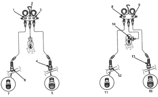
- 1. LOW PRESSURE VALVE
- 2. EVACUATION VALVE
- 3. HIGH PRESSURE VALVE
- 4. HIGH PRESSURE QUICK JOINT
- 5. 16 mm
- 6. LOW PRESSURE QUICK JOINT
- 7. 13 mm
- 8. LOW PRESSURE VALVE
- 9. HIGH PRESSURE VALVE
- 10. 16 mm
- 11. 13 mm
- 12. LOW PRESSURE JOINT
- 13. HIGH PRESSURE QUICK JOINT