PDF p. 1089 · 22-34
- 1.Remove the bolt, the ground terminal and the holder. Disconnect the field coil connector, then remove the thermal protector.
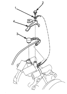
- 1. GROUND TERMINAL
- 2. 7.4 Nm (0.75 kgf/m, 5 lbf/ft)
- 3. THERMAL PROTECTOR
- 4. HOLDER
- 2.Replace the thermal protector with a new one and apply silicon sealant to the bottom of the thermal protector.
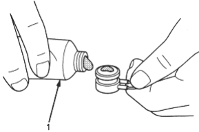
- 1. SILICONE SEALANT
- 3.Install in the reverse order of removal.
Relief Valve Replacement
- 1.Discharge the refrigerant (See Page 22-38).
- 2.Remove the relief valve and the O-ring. Plug the opening to keep foreign matter from entering the system and the compressor oil from running out.
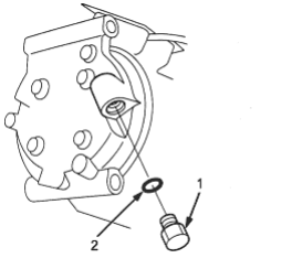
- 1. RELIEF VALVE, 9.8 Nm (1.0 kgf/m, 7.2 lbf/ft)
- 2. O-RING, Replace
- 3.Clean the mating surfaces.
- 4.Replace the O-ring with a new one at the relief valve and apply a thin coat of refrigerant oil before installing it.
- 5.Remove the plug and install the relief valve.
- 6.Charge the system (See Page 22-40) and test its performance (See Page 22-42).