PDF p. 1054 · 21-19
NOTE: LHD type is shown, RHD type is symmetrical.
- 1.Loosen the one mounting bolt as shown, and remove the wire harness clip, the mounting bolts and the steering hanger beam.
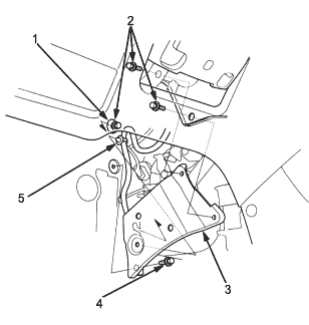
- 1. Loosen
- 2. 8 x 1.25 mm, 22 Nm (2.2 kgf/m, 16 lbf/ft)
- 3. STEERING HANGER BEAM PLATE
- 4. 8 x 1.25 mm, 22 Nm (2.2 kgf/m, 16 lbf/ft)
- 5. CLIP
- 2.Disconnect the connector from the blower motor, then remove the air hose, the self-tapping screws and the blower motor.
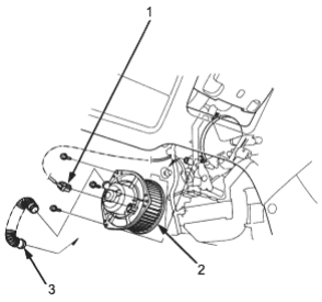
- 1. CONNECTOR
- 2. BLOWER MOTOR
- 3. AIR HOSE
- 3.Install in the reverse order of removal. make sure that there is no air leakage.
Mode Control
Adjustment
NOTE: LHD type is shown, RHD type is symmetrical.
- 1.From under the dash, disconnect the mode control cable housing from the clamp, and disconnect the mode control cable from the mode control linkage.
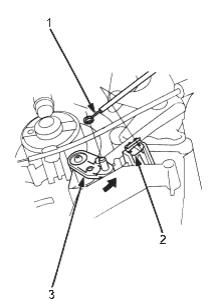
- 1. MODE CONTROL CABLE
- 2. CLAMP
- 3. MODE CONTROL LINKAGE
- 2.Set the mode control dial to VENT.
- 3.Turn the mode control linkage fully counter-clockwise as shown above and hold it. Attach the mode control cable to the mode control linkage, then snap the mode control cable housing into the clamp.