PDF p. 899 · 19-A-22
Disassembly
- 1.Remove the tension pins by pushing the retainer springs and turning them.
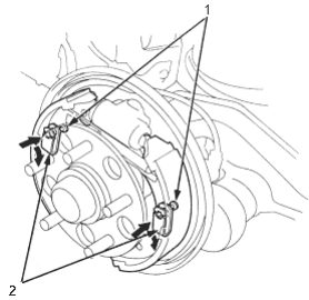
- 1. TENSIONER PINS
- 2. RETAINER SPRINGS
- 2.
Lower the brake shoe assembly and remove the lower return spring.
NOTE: Be careful not to damage the dust cover on the wheel cylinder.
- 3.Remove the brake shoe assembly.
- 4.Disconnect the parking brake cable from the parking brake lever.
- 5.Remove the upper return spring, self-adjusting lever and self-adjusting spring and separate the brake shoes.
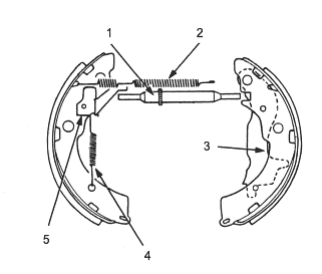
- 1. ADJUSTER BOLT, Check ratchet teeth for wear and damage
- 2. UPPER RETURN SPRING, Check for weakness and damage
- 3. PARKING BRAKE LEVER
- 4. SELF-ADJUSTER SPRING
- 5. SELF-ADJUSTER LEVER
- 6.Remove the wavy washer, parking brake lever and pivot pin from the brake shoe by removing the U-clip.
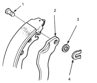
- 1. PIVOT PIN
- 2. PARKING BRAKE LEVER
- 3. WAVE WASHER
- 4. U-CLIP, Replace
Reassembly
- 1.Apply brake cylinder grease (P/N: 08733-B020R) or equivalent rubber grease to the sliding surface of the pivot pin and insert the pin into the brake shoe.
- 2.
Install the parking brake lever and wavy washer on the pivot pin and secure with U-clip.
NOTE: Pinch the U-clip securely to prevent the pivot pin from coming out of the brake shoe.
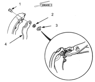
- 1. PIVOT PIN
- 2. WAVE WASHER
- 3. U-CLIP, Replace
- 4. PARKING BRAKE LEVER
PDF p. 900 · 19-A-23
- 3.Connect the parking brake cable to the parking brake lever.
- 4.Apply grease on each sliding surface.
- Apply brake cylinder grease (P/N: 08733-B020E) or equivalent rubber grease to the sliding surfaces as shown.
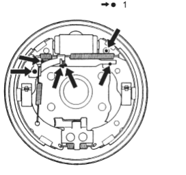
- 1. Sliding surface
- Apply Molykote 44MA to the brake shoe ends and opposite edges of the shoes as shown.
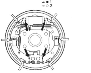
- 1. Brake shoe ends
- 2. Opposite edge of the shoe
- 5.Clean the threaded portions of clevis A and B. Coat the threads of the clevis with grease. To shorten the clevis, turn the adjuster bolt.
- 6.Hook the self-adjuster spring to the self -adjuster lever first, then to the brake shoe.
- 7.Install the clevis A and B and upper return spring noting the installation direction. Be careful no to damage the wheel cylinder dust covers.
- 8.Install the lower return spring.
- 9.Install the tension pins and retaining springs.
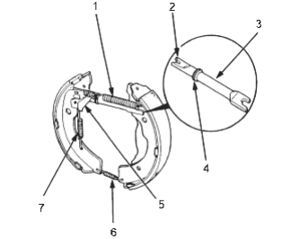
- 1. UPPER RETURN SPRING
- 2. CLEVIS B
- 3. CLEVIS A
- 4. ADJUSTER BOLT
- 5. SELF-ADJUSTER LEVER
- 6. LOWER RETURN SPRING
- 7. SELF-ADJUSTER SPRING
- 10.Install the brake drum.
- 11.If the wheel cylinder has been removed, bleed the brake system (See Page 19-A-7), and check for leaks at brake line connections, and retighten if necessary.
- 12.Depress the brake pedal several times to set the self-adjusting brake.
- 13.Adjust the parking brake (See Page 19-A-6).