PDF p. 890 · 19-A-13
- 1.Disconnect the brake fluid level switch connectors.
- 2.Remove the reservoir cap from the master cylinder.
- 3.Remove the brake fluid from the master cylinder reservoir with a syringe.
- 4.Disconnect the brake lines from the master cylinder.
- 5.Remove the master cylinder mounting nuts and washers.
- 6.Remove the master cylinder from the brake booster. Be careful not to bend or damage the brake lines when removing the master cylinder.
- 7.Remove the rod seal from the brake booster.
- 8.Remove the four booster mounting nuts.
- 9.Pull the brake booster forward until the clevis is clear of the bulkhead.
- 10.Remove the brake booster from the engine compartment.
- 11.Install the brake booster and master cylinder in the reverse order of removal and note the following items:
- Replace all rubber parts with new ones whenever, removed.
- Coat the lip of the new rod seal with recommended seal grease in the master cylinder set.
- Install the rod seal onto the brake booster with its grooved side toward the master cylinder.
- If replacing the master cylinder or brake booster, check and adjust the pushrod clearance before installing the master cylinder (See Page 19-A-17).
- 12.Fill the master cylinder reservoir and bleed the brake system (See Page 19-A-7).
- 13.After installation, check the brake pedal height and brake pedal free play (See Page 19-A-5) and adjust if necessary.
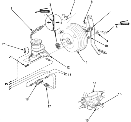
- 1. BRAKE FLUID LEVEL SWITCH CONNECTORS
- 2. Master cylinder side
- 3. ROD SEAL, Replace
- 4. Brake booster side
- 5. VACUUM HOSE
- 6. LOCK PIN, Replace
- 7. CLEVIS
- 8. CLEVIS PIN
- 9. 13 Nm (1.3 kgf/m, 9 lbf/ft)
- 10. GASKET, Replace
- 11. BRAKE BOOSTER
- 12. MASTER CYLINDER
- 13. To rear wheel cylinders
- 14. PROPORTIONING CONTROL VALVE (Without ABS)
- 15. RHD/LHD: To master cylinder secondary port
- 16. RHD/LHD: To master cylinder primary port
- 17. 15 Nm (1.5 kgf/m, 11 lbf/ft)
- 18. 4-WAY JOINT (With ABS)
- 19. To modulator unit
- 20. 15 Nm (1.5 kgf/m, 11 lbf/ft)
- 21. 15 Nm (1.5 kgf/m, 11 lbf/ft)