PDF p. 885 · 19-A-8
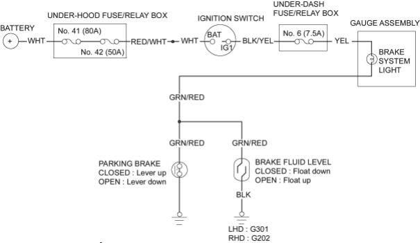
Parking Brake Switch Test
- 1.Remove the rear console and disconnect the connector from the switch.
- 2.Check for continuity between the positive terminal and body ground:
- With the brake lever up, there should be continuity.
- With the brake lever down, there should be no continuity.
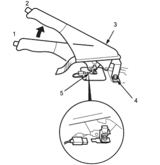
- 1. DOWN
- 2. UP
- 3. BRAKE LEVER
- 4. BODY GROUND
- 5. POSITIVE TERMINAL
Brake Fluid Level Switch Test
Brake Fluid Level Switch Test
- 1.Remove the reservoir cap. Check that the float moves up and down freely; if it doesn’t, replace the reservoir cap assembly.
- 2.Check for continuity between the terminals with the float in the down position and the up position:
- With the float up, there should be continuity.
- With the float down, there should be no continuity.
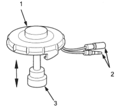
- 1. RESERVOIR CAP
- 2. TERMINALS
- 3. FLOAT