PDF p. 872 · 18-18
Note these items during replacement:
- Replace the self-locking nuts after removal.
- Any bolts or nuts connected to rubber mounts or bushings should be tightened with the vehicle on the ground.
- After installing the suspension arm, check the rear wheel alignment (See Page 18-4).
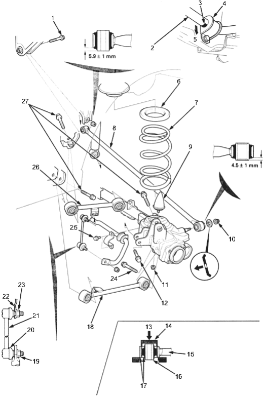
- 1. FLANGE BOLT, 10 x 1.25 mm, 54
Nm (5.5 kgf/m, 40 lbf/ft) - 2. STABILISER BAR. Align the stabiliser mark with end of stabiliser bushing.
- 3. DOWN
- 4. STABILISER BUSHING
- 5. MARK
- 6. SPRING UPPER SEAT. Check for deterioration and damage.
- 7. SPRING. Check for weakened compression and damage.
- 8. PANHARD ROD. Check for bending and damage.
- 9. BUMP STOP. Check for weakness
and damage. - 10. 12 x 1.25 mm, 74 Nm (7.5 kgf/m, 47 lbf/ft)
- 11. 10 x 1.25 mm, 39 Nm (4.0 kgf/m, 29 lbf/ft)
- 12. FLANGE NUT, 10 x 1.25 mm, 54 Nm (5.5 kgf/m, 40 lbf/ft)
- 13. Press
- 14. DRIVER ATTACHMENT, 30.8 x 45
mm, 07947-6890300 - 15. UPPER/LOWER LINK
- 16. FRONT/REAR BUSHING. Check for deterioration and damage.
- 17. Machined surface.
- 18. LOWER LINK.
♦ Check for bending and damage.
♦ Check bushings for deterioration
and damage. - 19. SELF-LOCKING NUT, 10 x 1.25 mm, 38 Nm (3.9 kgf/m, 28 lbf/ft). Replace. hold the ball joint pin using a hex wrench, and tighten the self-locking nut.
- 20. BOOT Check for deterioration and damage.
- 21. STABILISER LINK. Inspect for faulty movement and wear.
- 22. BODY
- 23. FLANGE NUT, 10 x 1.25 mm, 29 Nm (3.0 kgf/m, 22 lbf/ft). Before tightening the flange nut, position the ball joint pin in the middle of its range of travel, with the suspension under vehicle load.
- 24. FLANGE BOLT, 12 x 1.25 mm, 64
Nm (6.5 kgf/m, 47 lbf/ft) - 25. 8 mm BOLT, 22 Nm (2.2 kgf/m, 16 lbf/ft)
- 26. UPPER LINK
♦ Check for bending and damage.
♦ Check the bushings for deterioration and damage. - 27. FLANGE BOLT, 12 x 1.25 mm, 64
Nm (6.5 kgf/m, 47 lbf/ft)