PDF p. 869 · 18-15
Removal
- 1.Remove the front wheels.
- 2.Remove the wheel sensor wire from the knuckle and damper. Do not disconnect the wheel sensor connector.
- 3.Separate the stabiliser bar from the lower arm (step 20 on (See Page 18-120).
- 4.Remove the brake hose bracket from the damper.
- 5.Remove the damper pinch bolt and pull out the knuckle from the damper end.
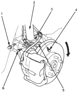
- 1. DAMPER PINCH BOLT
- 2. DAMPER
- 3. KNUCKLE
- 4. FLANGE BOLT, 8 x 1.25 mm
- 5. WHEEL SENSOR WIRE
- 6. 6 mm FLANGE BOLT
- 6.Remove the damper by removing the three flange nuts.
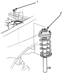
- 1. FLANGE NUT, 10 x 1.25 mm
- 2. DAMPER ASSEMBLY
Disassembly/Inspection
Disassembly
- 1.Compress the damper spring with the spring compressor according to the manufacturer’s instructions. Do not compress the spring more than necessary.
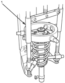
- 1. STRUT SPRING COMPRESSOR: (Commercially available) BRANICK© T/N MST-580A or Model 7200 or equivalent
- 2.Hold the damper rod using the hex wrench and remove the 12 mm self-locking nut.
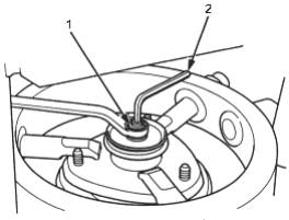
- 1. 12 mm SELF-LOCKING NUT. Replace.
- 2. HEX WRENCH
- 3.Release the pressure from the spring compressor then disassemble the damper as shown on the next page.
PDF p. 870 · 18-16
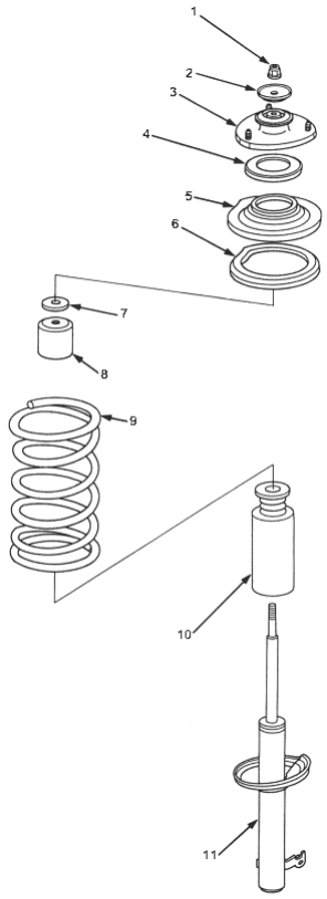
- 1. SELF-LOCKING NUT, 12 x 1.25 mm. Replace. 44 Nm (4.5 kgf/m, 33 lbf/ft)
- 2. DAMPER MOUNTING WASHER
- 3. DAMPER MOUNTING BASE
- 4. DAMPER MOUNTING BEARING. Check for any play or roughness.
- 5. SPRING UPPER SEAT
- 6. SPRING MOUNTING RUBBER. Check for deterioration and damage.
- 7. DUST COVER PLATE
- 8. DUST COVER. Check for bending and damage.
- 9. DAMPER SPRING. Check for weakened compression and damage.
- 10. BUMP STOP. Check for weakness and damage.
- 11. DAMPER UNIT
Inspection
- 1.Reassemble all parts, except the spring.
- 2.Push on the damper assembly as shown.
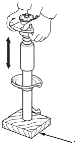
- 1. WOODEN BLOCK
- 3.Check for smooth operation through a full stroke, both compression and extension. The damper should move smoothly. If it does not (no compression or extension) the gas is leaking and the damper should be replaced.
- 4.Check for oil leaks, abnormal noises or binding during these tests.
PDF p. 871 · 18-17
Reassembly
- 1.Install the damper unit on a spring compressor.
- 2.Assemble the damper in reverse order of removal except the damper mounting washer and self-locking nut. Align the bottom of the damper spring and spring lower seat as shown.
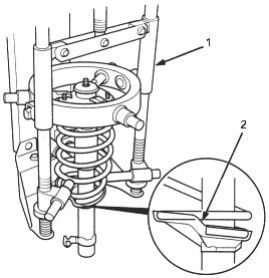
- 1. STRUT SPRING COMPRESSOR: (Commercially available) BRANICK© T/N MST-580A or Model 7200 or equivalent
- 2. SPRING LOWER SEAT
- 3.Compress the damper spring.
- 4.Install the damper mounting washer and a new 122 mm self-locking nut.
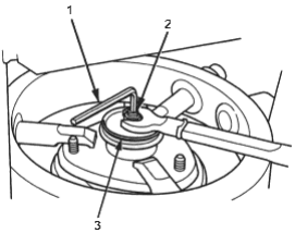
- 1. HEX WRENCH
- 2. SELF-LOCKING NUT, 12 x 1.25 mm. Replace. 44 Nm (4.5 kgf/m, 33 lbf/ft)
- 3. DAMPER MOUNTING WASHER
- 5.Hold the damper rod using a hex wrench and tighten the 12 mm self-locking nut.
Installation
- 1.Loosely install the damper on the frame with the aligning tab facing inside, then loosely install the two flange nuts.
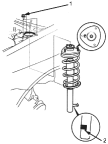
- 1. FLANGE NUT, 10 x 1.25 mm, 69 Nm (7.0 kgf/m, 51 lbf/ft)
- 2. ALIGNING TAB
- 2.Insert the damper in the knuckle so that the aligning tab is aligned with the slot in the knuckle.
- 3.Loosely install the damper pinch bolt on the top of the knuckle.
- 4.Install the brake hose bracket on the damper.
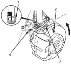
- 1. DAMPER PINCH BOLT, 74 Nm (7.5 kgf/m, 54 lbf/ft)
- 2. FLANGE BOLT, 8 x 1.25 mm, 22 Nm (2.2 kgf/m, 16 lbf/ft)
- 3. WHEEL SENSOR WIRE
- 4. 6 mm FLANGE BOLT, 9.8 Nm (1.0 kgf/m, 7.2 lbf/ft)
- 5.Loosely install the stabiliser bar on the lower arm (see step 20 on Page 18-12).
- 6.Install the wheel sensor wire on the knuckle and damper.
- 7.Raise the knuckle with a floor jack until the vehicle just lifts off the safety stand.
- 8.Tighten the damper pinch bolt.
- 9.Tighten the flange nuts on the top of the damper.
- 10.Tighten the 8 mm self-locking nut on the stabiliser bar.
- 11.Install the front wheel.
- 12.Check the front wheel alignment and adjust if
necessary (See Page 18-4).