PDF p. 862 · 18-9
Note the following items during replacement:
- Use only genuine Honda wheel weights for aluminium wheels. Non-genuine wheel weights may corrode and damage the aluminium wheels
- On the aluminium wheels remove the centre cap from the inside of the wheel after removing the wheel.
- before installing the brake disc, clean the mating surfaces of the front hub and brake disc.
- before installing the wheel, clean the mating surfaces of the brake disc and wheel.
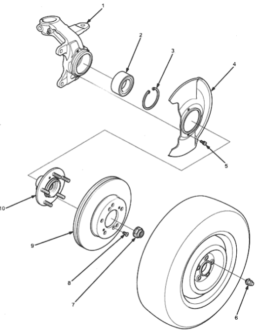
- 1.KNUCKLE
- 2.WHEEL BEARING. Replace.
- 3.CIRCLIP
- 4.SPLASH GUARD
- 5.SCREW, 5 x 0.8 mm, 5.9 Nm (0.6 kgf/m, 4.3 lbf/ft)
- 6.WHEEL NUT, 12 x 1.5 mm, 108 Nm (11.0 kgf/m, 80 lbf/ft)
- 7.
SPINDLE NUT, 22 x 1.5 mm, 181 Nm
(18.5 kgf/m, 134 lbf/ft). Replace.
- Before installing the spindle nut, apply engine oil to the seating surface of the nut.
- After tightening use a drift to stake the spindle nut shoulder against the spindle.
- 8.6 mm BRAKE DISC RETAINING SCREW, 9.8 Nm (1.0 kgf/m, 7 lbf/ft)
- 9.BRAKE DISC. Check for wear and rust. Inspection see section 19.
- 10.FRONT HUB. Check for damage and cracks.
PDF p. 863 · 18-10
- 1.Loosen the wheel nuts slightly.
- 2.Raise the front of the vehicle and support it with safety stands in the proper locations (see section 1).
- 3.Remove the wheel nits and wheel.
- 4.Raise the locking tab on the spindle nut, then remove the nut.
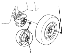
- 1. WHEEL NUT, 108 Nm (11 kgf/m, 80 lbf/ft)
- 2. SPINDLE NUT, 22 x 1.5 mm, 181 Nm (18.5 kgf/m, 134 lbf/ft). Replace. NOTE: After tightening use a drift to stake the spindle nut shoulder against the spindle.
- 5.Remove the brake hose mounting bolts.
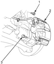
- 1. BRAKE HOSE MOUNTING BOLT, 8 x 1.25 mm, 22 Nm (2.2 kgf/m, 16 lbf/ft)
- 2. CALIPER
- 3. CALIPER MOUNTING BOLTS, 12 x 1.25 mm, 108 Nm (11.0 kgf/m, 80 lbf/ft)
- 6.Remove the caliper mounting bolts and hang the caliper assembly to one side. To prevent accidental damage to the caliper assembly or brake hose, use a short piece of wire to hang the caliper from the undercarriage.
- 7.Remove the 6 mm brake disc retaining screws.
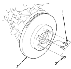
- 1. 8 x 1.25 mm Bolts
- 2. 6 mm BRAKE DISC RETAINING SCREWS, 9.8 Nm (1.0 kgf/m, 7.2 lbf/ft)
- 3. BRAKE DISC
- 8.Screw two 8 x 1.25 mm bolts into the disc to push it away from the hub. Turn each bolt two turns at a time to prevent cocking the disc excessively.
- 9.Remove the brake disc from the knuckle.
- 10.Check the front hub for damage and cracks.
- 11.Remove the wheel sensor from the knuckle. Do not disconnect the wheel sensor connector (for vehicles with ABS).
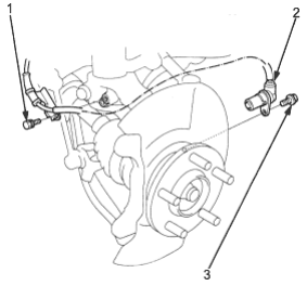
- 1. 9.8 Nm (1.0 kgf/m, 7.2 lbf/ft)
- 2. WHEEL SENSOR
- 3. SENSOR MOUNTING BOLT, 21 Nm (2.2 kgf/m, 16 lbf/ft)
PDF p. 865 · 18-11
- 12.Clean any dirt or grease off the ball joint.
- 13.Remove the cotter pin from the steering arm and remove the nut.
- 14.Apply grease to the special tool on the areas shown. This will ease installation of the tool and prevent damage to the pressure bolt threads.
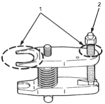
- 1. Apply grease here.
- 2. PRESSURE BOLT
- 15.Loosen the 12 mm nut on the tie-rod end ball joint. Be sure that the nut is flush with the ball joint pin end to prevent damage to the threaded end of the ball joint.
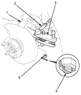
- 1. KNUCKLE
- 2. TIE-ROD
- 3. BALL JOINT REMOVER, 28 mm, 07MAC - SL00200
- 4. COTTER-PIN. Replace. On reassembly bend the cotter pin as shown.
- 5. NUT, 12 x 1.25 mm, 43 Nm (4.4 kgf/m, 32 lbf/ft)
- 16.Install the special tool as shown. Insert the jaws carefully making sure you do not damage the ball joint boot. Adjust the jaw spacing by turning the pressure bolt. If necessary, apply penetrating type lubricant to loosen the ball joint.
- 17.Once the special tool is in place turn the adjusting bolt as necessary to make the jaws parallel. Then hand-tighten the pressure bolt and recheck the jaws to make sure they are still parallel.
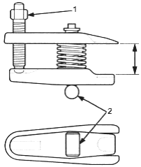
- 1. PRESSURE BOLT
- 2. ADJUSTING BOLT
After making the adjustment to the adjusting bolt, be sure the head of the adjusting bolt is in this position to allow the jaw to pivot.
- 18.With a wrench tighten the pressure bolt until the ball joint shaft pops loose from the steering bolt.
- 19.Remove the tool then remove the nut from the end of the ball joint and pull the ball joint out of the steering/suspension arm. Inspect the ball joint boot and replace it if damaged.
PDF p. 866 · 18-12
- 20.Remove the 8 mm self-locking nut and separate the stabiliser link from the lower arm.
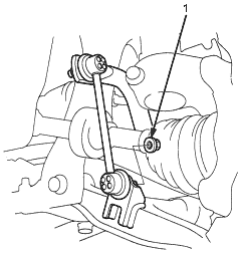
- 1. SELF-LOCKING NUT, 10 x 1.25 mm, 29 Nm (3.0 kgf/m, 22 lbf/ft). Replace.
- 21.Remove the clip from the lower arm ball joint castle nut and remove the nut.
- 22.Install a 12 mm hex nut on the ball joint. Be sure that the hex nut is flush with the ball joint pin end, or the threaded section of the ball joint pin might be damaged by the ball joint remover.
- 23.Use the special tool (See Page 18-12) to separate the ball joint and knuckle. If necessary, apply penetrating type lubricant to loosen the ball joint.
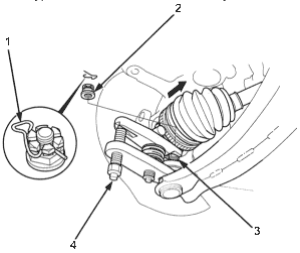
- 1. CLIP. Replace. Make sure the clip is seated securely in the nut when installing the clip.
- 2. CASTLE NUT, 12 x 1.25 mm, 49 - 59 Nm ( 5.0 - 6.0 kgf/m, 36 - 43 lbf/ft)
- 3. 12 mm HEX NUT
- 4. BALL JOINT REMOVER, 28 mm, 07MAC - SL00200
- 24.Remove the damper pinch bolt and pull out the knuckle from the damper end.
- 25.Pull the knuckle outward and remove the driveshaft outboard joint from the knuckle by tapping the driveshaft end with a plastic hammer then remove the knuckle.
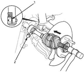
- 1. ALIGNING TAB
NOTE: On reassembly align the slot on the knuckle and aligning tab on the damper. - 2. DAMPER PINCH BOLT, 74 Nm (7.5 kgf/m, 54 lbf/ft)
- 26.Separate the hub from the knuckle using the bearing separator and a hydraulic press.
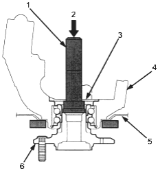
- 1. DRIVER, 07749 - 0010000
- 2. Press
- 3. DRIVER ATTACHMENT, 42 x 47 mm, 07746 - 0010300
- 4. KNUCKLE
- 5. SPLASH GUARD
- 6. FRONT HUB
- 27.Remove the circlip and the splash guard from the knuckle.
PDF p. 867 · 18-13
- 28.Press the wheel bearing out of the knuckle using the special tools and a press.
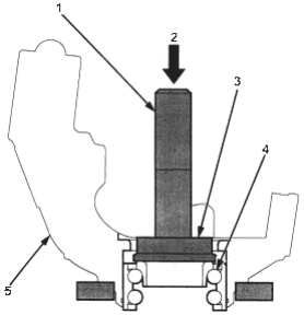
- 1. DRIVER, 07749 - 0010000
- 2. Press
- 3. DRIVER ATTACHMENT B, 07947 - 6340201
- 4. WHEEL BEARING. Replace.
- 5. KNUCKLE
- 29.Press the wheel bearing inner race from the hub using a socket of suitable diameter and a bearing separator.
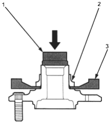
- 1. SOCKET, Socket End Dia. 45 mm
- 2. WHEEL BEARING INNER RACE
- 3. BEARING SEPARATOR, (Commercially available)
- 30.Wash the knuckle and hub thoroughly in high flash point solvent before reassembly.
- 31.Press a new wheel bearing into the knuckle using the old bearing, a plate, the special tool and a press. Place the wheel bearing on the knuckle with the pack seal facing (metal colour) towards the inside. Be careful not to damage the sleeve of the pack seal.
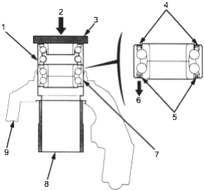
- 1. OLD BEARING
- 2. Press
- 3. PLATE
- 4. DOUBLE LIP SEAL (BLACK COLOUR)
- 5. PACK SEAL (METAL COLOUR)
- 6. INSIDE
- 7. NEW WHEEL BEARING
- 8. SUPPORT BASE. 07965 - SD90100
- 9. KNUCKLE
- 32.Install the circlip securely in the knuckle groove.
- 33.Install the splash guard and tighten the screws.
- 34.Install the hub on the knuckle using the special tools shown and a hydraulic press. Be careful not to distort the splash guard.
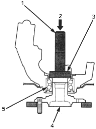
- 1. DRIVER, 07749 - 0010000
- 2. Press
- 3. DRIVER ATTACHMENT B, 07947 - 6340201
- 4. FRONT HUB
- 5. WHEEL BEARING
PDF p. 868 · 18-14
- 35.Install the knuckle in the reverse order of removal and pay particular attention to the following items:
- Be careful not to damage the ball joint boots when installing the knuckle.
- Torque all mounting hardware to the specified torque values.
- Torque the castle nuts to the lower torque specifications, then tighten them only far enough to align the slot with the pin hole. Do not align the castle nut by loosening.
- Install new cotter pins on the castle nuts after torquing.
- Avoid twisting the sensor wires when installing the wheel sensor.
- Before installing the brake disc clean the mating surfaces of the front hub and the inside of the brake disc.
- Before installing the spindle nut, apply a small amount of motor oil to the seating surface of the nut. After tightening use a drift to stake the spindle nut shoulder against the drive shaft.
- Before installing the wheel, clean the mating surface of the brake disc and the inside of the wheel.
- Check the front wheel alignment and adjust it if necessary (See Page 18-4).
Ball Joint Boot Replacement
- 1.Remove the boot from the lower arm and wipe the old grease off the ball pin.
- 2.Pack the lower area of the ball pin with fresh grease.
- 3.Pack the interior of the new boot and lip with fresh grease.
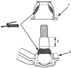
- 1. BOOT INSTALLATION SECTION. Wipe off the grease.
- 2. BALL PIN TAPERED SECTION. Wipe of the grease.
- 3. BOOT INSTALLATION SECTION. Wipe off the grease.
- 4.
Drive the new boot using the special tool as shown below.
NOTE: There must not be a gap between the boot installation sections.
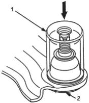
- 1. Hub Dis/Assembly TOOL ATT, 45 x 36 x 57
- 2. LOWER ARM
- 5.After installation, perform the following checks:
- Check the boot for damage, and boot installation section for distortion.
- Check that there is no gap between the boot and joint housing.
necessary.