PDF p. 861 · 18-8
Note the following items during replacement:
- Replace the self-locking nuts after removal.
- The vehicle should be on the ground before any bolts or nuts connected to rubber mounts or bushings are tightened.
- Before tightening the upper and lower mounting nuts on the stabiliser link, adjust the location of the link with the suspension under vehicle load.
- After installing the suspension arm, check the front wheel alignment and adjust if necessary (See Page 18-5).
- When the stabiliser bar is exchanged the connection of the left ball joint and knuckle is removed.
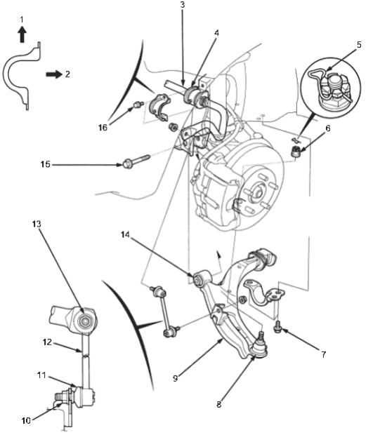
- 1. UP
- 2. BODY
- 3. STABILISER BAR, Check for bending and damage.
- 4. STABILISER BUSHING, Check for bending and damage.
- 5. CLIP. Replace. Make sure the clip is seated securely in the nut as shown.
- 6. CASTLE NUT, 12 x 1.25 mm, 49 - 59 Nm (5.0 - 6.0 kgf/m, 36 -43 lbf/ft)
- 7. FLANGE BOLT, 12 x 1.25 mm, 88
Nm (9.0 kgf/m, 65 lbf/ft) - 8. BALL JOINT BOOT. Check for deterioration and damage
Boot replacement, (See Page 18-14). - 9. LOWER ARM. Check for damage.
- 10. SELF-LOCKING NUT, 10 x 1.25 mm, 29 Nm (3.0 kgf/m, 22 lbf/ft). Hold the ball joint pin using a hex wrench and tighten the self-locking nut.
- 11. BOOT. Check for deterioration and damage.
- 12. STABILISER LINK. Check for bending and damage.
- 13. SELF-LOCKING NUT, 10 x 1.25 mm, 38 Nm (3.9 kgf/m, 28 lbf/ft). Hold the ball joint pin using a hex wrench and tighten the self-locking nut.
- 14. LOWER ARM RUBBER BUSHING. Check for deterioration and damage.
- 15. FLANGE BOLT, 14 x 1.5 mm, 103
Nm (10.5 kgf/m, 76 lbf/ft) - 16. FLANGE BOLT, 8 x 1.25 mm, 22 Nm (2.2 kgf/m, 16 lbf/ft)