PDF p. 824 · 17-29
Replacement
- 1.Place a suitable container under the vehicle.
- 2.Drain the power steering fluid from the reservoir.
- 3.Remove the belt by loosening the pump mounting bolt and lock bolt.
- 4.Cover the A/C compressor with several shop towels to protect it from spilled power steering fluid. Disconnect the pump inlet hose and supply line from the pump, and plug them. Take care not to spill the fluid on the body or parts. Wipe off any spilled fluid at one.
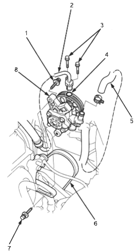
- 1. PUMP MOUNTING BOLT, 24 Nm (2.4 kgf/m, 17 lbf/ft)
- 2. SUPPLY LINE
- 3. 11 Nm (1.1 kgf/m, 8 lbf/ft)
- 4. O-RING, Replace
- 5. PUMP INLET HOSE
- 6. PUMP BELT
- 7. PUMP LOCK BOLT, 24 Nm (2.4 kgf/m, 17 lbf/ft)
- 8. PUMP
- 5.Remove the pump mounting bolts and lock bolt, then remove the pump. Do not turn the steering wheel with the pump removed.
- 6.Cover the opening of the pump with a piece of tape to prevent foreign material from entering the pump.
- 7.Connect the pump inlet hose and supply line. Tighten the pump fittings securely.
- 8.Loosely install the pump in the pump bracket with mounting bolt and lock bolt.
- 9.
Install the pump belt.
Note these items during belt installation:
- Make sure that the power steering belt is positioned properly on the pulleys.
- Do not get power steering fluid or grease in the power steering belt or pulley faces. Clean off any fluid or grease before installation.
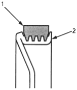
- 1. POWER STEERING BELT
- 2. PULLEY
- 10.Adjust the pump belt (See Page 17-16).
- 11.Fill the reservoir to the upper level line (See Page 17-18).
PDF p. 825 · 17-30
Disassembly
Note these items during disassembly:
- The power steering components are made of aluminium. Avoid damaging the components during assembly.
- Clean the disassembled parts with a solvent, and dry them with compressed air. Do not dip the rubber parts in a solvent.
- Always replace the O-rings and rubber seals with new ones before assembly.
- Apply recommended power steering fluid to the parts indicated in the assembly procedures.
- Do not allow dust, dirt, or other foreign materials to enter the power steering system.
- Replace the pump as an assembly if the parts indicated with asterisk (*) are worn or damage.
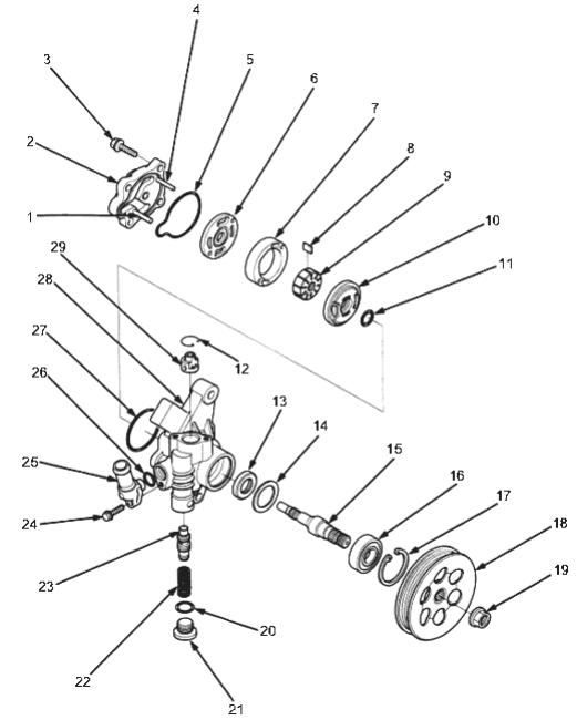
- 1. 5 mm ROLLER
- 2. *PUMP COVER
- 3. FLANGE BOLTS
20 Nm (2.0 kgf/m, 14 lbf/ft) - 4. 4.5 mm ROLLER
- 5. PUMP COVER SEAL
Replace - 6. *OUTER SIDE PLATE
- 7. *PUMP CAM RING
- 8. *PUMP VANES
(10 Plates) - 9. *PUMP ROTOR
- 10. *SIDE PLATE
- 11. 13 x 1.9 mm O-RING
Replace - 12. *SNAP RING
- 13. PUMP SEAL
Replace - 14. PUMP SEAL SPACER
- 15. PUMP DRIVE SHAFT
- 16. BALL BEARING
- 17. 40 mm CIRCLIP
- 18. PULLEY
- 19. PULLEY NUT
64 Nm (6.5 kgf/m, 47 lbf/ft) - 20. 16.7 x 1.8 mm O-RING Replace
- 21. *FLOW CONTROL VALVE CAP 49 Nm (5.0 kgf/m, 36 lbf/ft)
- 22. *SPRING
- 23. *FLOW CONTROL VALVE Inspection (See Page 17-31)
- 24. FLANGE BOLTS
11 Nm (1.1kgf/m,. 8 lbf/ft) - 25. INLET JOINT
- 26. 15.2 x 2.4 mm O-RING
- 27. 51 x 2.4 mm O-RING
- 28. *PUMP HOUSING
- 29. *SUB-VALVE
PDF p. 826 · 17-31
- 1.Drain the fluid from the pump.
- 2.Hold the steering pump in a vice with soft jaws, hold the pulley with the extension bar, and remove the pulley nut and pulley. Be careful not to damage the pump housing with the jaws of the vice.
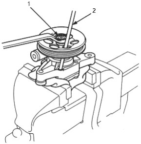
- 1. PULLEY NUT
- 2. EXTENSION BAR: (Commercial available)
- 3.Loosen the flow control valve cap with a hex wrench and remove it.
- 4.Remove the O-ring, flow control valve and spring.
- 5.Remove the inlet joint and O-ring.
- 6.Remove the pump cover and pump cover seal.
- 7.Remove the pump cover and pump cover seal.
- 8.Remove the out side plate, pump cam ring, pump rotor, pump vanes, side plate and O-rings.
- 9.Remove the circlip, then remove the pump drive shaft by tapping the shaft end with the plastic hammer.
- 10.Remove the pump seal spacer and pump seal.
Inspection
Flow Control Valve
- 1.Check the flow control valve for wear, burrs, and other damage to the edges of the grooves in the valve
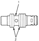
- 1. FLOW CONTROL VALVE
- 2. Check for damage to edges
- 2.Inspect the bore of the flow control valve for scratches or wear.
- 3.Slip the valve back in the pump, and check that it moves in and out smoothly.
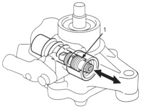
- 1. FLOW CONTROL VALVE
If OK, go to step 4, if not, replace the pump as an assembly. The flow control valve is not available separately.
PDF p. 827 · 17-32
- 4.Attach a hose to the end of the valve. Submerge the valve in a container of power steering fluid or solvent, and blow in the hose. If air bubbles leak through the valve at less than 98 kPa (1.0 kgf/cm2, 14.2 psi), replace the pump as an assembly.
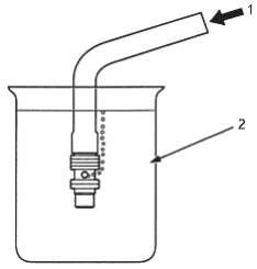
- 1. AIR PRESSURE
- 2. POWER STEERING FLUID or SOLVENT
If the flow control valve tests OK, reinstall it in the pump. If the flow control valve still leaks air, replace the pump as an assembly. The flow control valve is not available separately.
Ball Bearing
- 1.Inspect the ball bearing by rotating the out race slowly, if any play or roughness is felt, replace the ball bearing.
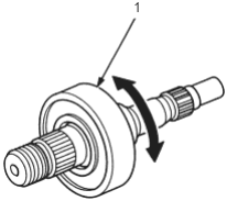
- 1. BALL BEARING
- 2.Replace the ball bearing using a press
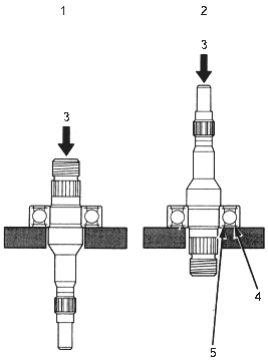
- 1. REMOVAL
- 2. INSTALL
- 3. PRESS
- 4. INSTALL WITH THE RED SHIELDED SIDE FACING DOWN.
- 5. NOTE: SUPPORT THE INNER RACE WITH THE TOOL SECURELY.
PDF p. 828 · 17-33
Reassembly
- 1.Align the pin of the sub-valve with the oil passage in pump housing, and push down the sub-valve. Install the snap ring properly.
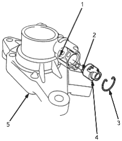
- 1. OIL PASSAGE, Align the pin of sub-valve with the oil passage.
- 2. PIN
- 3. SNAP RING
- 4. SUB-VALVE
- 5. PUMP HOUSING
- 2.Install the new pump seal with its grooved side facing in into the pump housing by hand, then install the pump seal spacer.
- 3.Position the pump drive shaft in the pump housing, then drive it in using a socket wrench as shown.
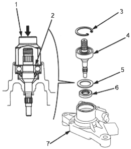
- 1. SOCKET WRENCH
- 2. BALL BEARING
- 3. 40 mm CIRCLIP
- 4. PUMP DRIVE SHAFT
- 5. PUMP SEAL SPACER
- 6. PUMP SEAL, Replace
- 7. PUMP HOUSING
- 4.Install the 40 mm circlip with its radiused side facing out.
- 5.Coat the pump cover seal with power steering fluid, and install it into the groove in the pump cover.
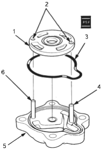
- 1. OUTER SIDE PLATE
- 2. ROLLER SET HOLES
- 3. PUMP COVER SEAL, Replace
- 4. 5 mm ROLLER
- 5. PUMP COVER
- 6. 4.5 mm ROLLER
- 6.Install the out side plate over the two rollers.
- 7.Set the pump cam ring over the two rollers with the “o” mark on the cam ring upward.
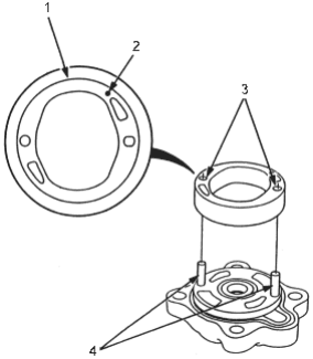
- 1. PUMP CAM RING
- 2. MARK
- 3. ROLLER SET HOLES
- 4. ROLLERS
PDF p. 829 · 17-34
- 8.Assemble pump rotor to the pump cover.
- 9.Set the 10 vanes in the grooves in the rotor. Make sure that the round ends of the vanes are in contact with the sliding surface of the cam ring
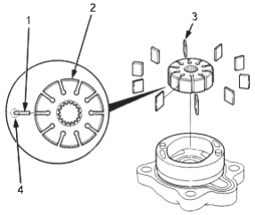
- 1. VANE
- 2. PUMP ROTOR
- 3. PUMP VANES, (10 plates)
- 4. ROUND END
10 Coat the O-ring with power steering fluid, and install it
into the grooves in the side plate.
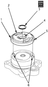
- 1. ROLLER SET HOLE
- 2. SIDE PLATE
- 3. 15.2 x 2.4 mm O-RING, Replace
- 4. Grooves
- 5. ROLLER SET HOLE
- 6. ROLLERS
- 11.Install the side plate on the cam ring by aligning the roller set holes in the side plate with the rollers.
- 12.Coat the O-ring with power steering fluid, and position it into the pump housing.
- 13.Install the pump cover assembly in the pump housing.
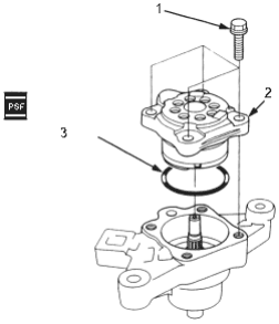
- 1. FLANGE BOLTS, 20 Nm (2.0 kgf/m, 14 lbf/ft)
- 2. PUMP COVER ASSEMBLY
3. 51 x 2.4 mm O-RING, Replace
- 14.Coat the flow control valve with power steering fluid.
- 15.Install the flow control valve and spring in the pump housing.
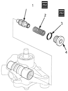
- 1. FLOW CONTROL VALVE
- 2. SPRING
3 16.7 x 1.8 mm O-RING, Replace
- 4.FLOW CONTROL VALVE CAP, 49 Nm (5.0 kgf/m, 36 lbf/ft)
- 16.Coat the O-ring with power steering fluid, and install it on the flow control valve cap.
- 17.Install the flow control valve cap on the pump housing, and tighten it.
PDF p. 830 · 17-35
- 18.Coat the O-ring with power steering fluid, and install it into the grooves in the inlet joint.
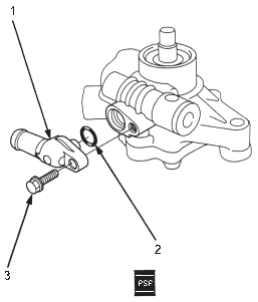
- 1. INLET JOINT
- 2. 15.2 x 2.4 mm O-RING ,Replace
- 3. FLANGE BOLTS, 11 Nm (1.1 kgf/m, 8 lbf/ft)
19 Install the inlet joint on the pump housing.
- 20.Install the pulley as shown below, then loosely install the pulley nut. Hold the steering pump in a vice with soft jaws. Be careful not to damage the pump housing with the jaws of the vice.
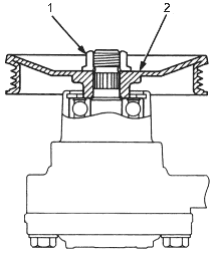
- 1. PULLEY NUT
- 2. PULLEY
- 21.Hold the pulley with the extension bar, and tighten the pulley nut.
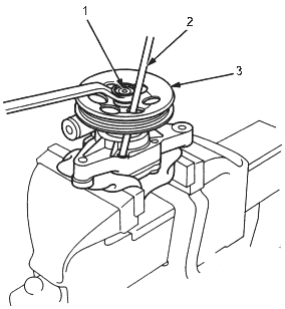
- 1. PULLEY NUT, 64 Nm (6.5 kgf/m, 47 lbf/ft)
- 2. EXTENSION BAR: (Commercially available)
- 3. PULLEY
- 22.Check that the pump turns smoothly by turning the pulley.