PDF p. 831 · 17-36
Removal
Note these items during removal:
- Using solvent and a brush, wash any oil and dirt off of the valve body unit its lines, and the end if the gearbox. Blow dry with compressed air.
- Be sure to remove the steering wheel before disconnecting the steering joint. Damage to the cable reel can occur.
- 1.Drain the power steering fluid as described (See Page 17-18).
- 2.Raise the front of vehicle, and make sure it is securely supported.
- 3.Remove the front wheels.
- 4.Remove the driver’s airbag assembly (see section 24).
- 5.Remove the steering wheel (See Page 17-20).
- 6.Remove the steering joint cover.
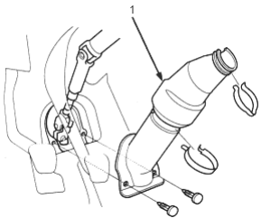
- 1. STEERING JOINT COVER
- 7.Remove the steering joint bolts, and disconnect the steering joint by moving the steering joint toward the column.
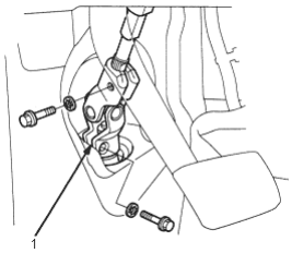
- 1. STEERING JOINT
- 8.Remove the cotter pin from the 12 mm nut and loosen the nut.
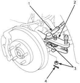
- 1. TIE-ROD END
- 2. BALL JOINT REMOVER, 28 mm, 07MAC-SL00200
- 3. 12 mm NUT
- 4. COTTER PIN, Replace
- 9.Separate the tie-rod ball joint and knuckle using the special tool (see section 18 for tool instructions).
- 10.Loosen the 14 mm flare nut, and disconnect the supply line. Remove the supply line clamp.
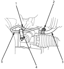
- 1. 14 mm FLARE NUT
- 2. ADJUSTABLE HOSE CLAMP
- 3. RETURN HOSE
- 4. SUPPLY LINE CLAMP
- 5. SUPPLY LINE
- 11.Loosen the adjustable hose clamp and disconnect the return hose.
- 12.
After disconnecting the hoses and lines, plug or seal them with a piece of tape or equivalent to prevent foreign materials from entering the valve body unit.
NOTE: Do not loosen the cylinder lines between the valve body unit and cylinder.
PDF p. 832 · 17-37
- 13.Disconnect the right and left stabiliser spring to the stabiliser link
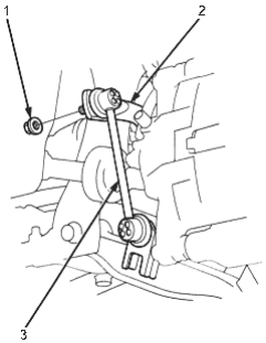
- 1. 10 mm SELF-LOCK NUT, Replace
- 2. STABILISER SPRING
- 3. STABILISER LINK
- 14.Disconnect the right and left lower arms to the knuckle (see section 18).
- 15.Remove the stabiliser holders and mounting bushings.
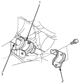
- 1. STABILISER BUSHING
- 2. STABILISER HOLDER
- 3. STABILISER SPRING
- 16.
Swing the knuckle forward. Turn the stabilizer spring to bring the stabilizer end to underside of the drive shaft.
Bring the stabilizer spring of the opposite side to the underside of the driveshaft, too.
Lower the lower arm and bring the stabilizer end to the underside of the lower arm.
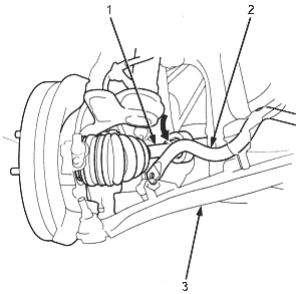
- 1. DRIVESHAFT
- 2. STABILISER SPRING
- 3. LOWER ARM
- 17.
Tilt the stabiliser spring aslant. Remove the stabiliser spring by pulling it to the passenger’s side while turning the spring.
NOTE: The stabiliser spring is different for installation on the right/left sides. Mark the spring not to interchange it during installation.
- 18.Grasp the assistant’s side tie-rod, and pull the rack all the way to the passenger’s side.
PDF p. 833 · 17-38
- 19.
Remove the 10 mm attaching bolts of the steering gearbox mounting bracket B. Do not remove the bracket. For vehicle’s with RHD only; remove the supply line clamp from the bracket B.
LHD:
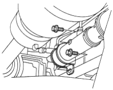
RHD:
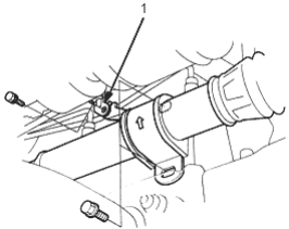
- 1. SUPPLY LINE CLAMP
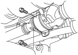
- 20.Remove the 10 mm attaching bolts of the steering gearbox mounting bracket A. Do not remove the bracket.
21 Disconnect the shift cable (CVT only) from transmission
(see section 14).
- 22.Move the steering gearbox toward the passenger’s side frame hole and pulling it.
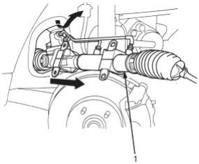
- 1. STEERING GEARBOX
- 23.Remove the steering gearbox by pulling it to the passenger’s side while tilting the gearbox.
- 24.Remove the steering gearbox mounting brackets and mounting cushions.
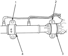
- 1. MOUNTING BRACKET B
- 2. MOUNTING BRACKET A
- 3. MOUNTING CUSHION A
- 4. MOUNTING CUSHION B
PDF p. 834 · 17-39
Disassembly
Steering Rack Disassembly
Note these items during disassembly:
- Before disassemble of the gearbox, wash it off with solvent and a brush.
- Do not dip seals and O-rings in solvent.
- 1.Remove the steering gearbox (See Page 17-36).
- 2.Remove the tie-rod end and locknut.
- 3.Remove the boot bands and the tie-rod clips. Pull the boots away from the ends of the gearbox.
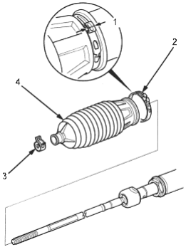
- 1. CUT
- 2. BOOT BAND, Replace
- 3. TIE-ROD CLIP
- 4. BOOT
- 4.Unbend the lock washer
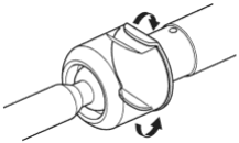
- 5.Unscrew both rack ends with a wrench. Be careful not to damage the rack surface with the wrench. Remove the lock washer.
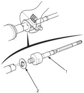
- 1. RACK END
- 2. LOCK WASHER, Replace
- 6.Loosen the locknut, then remove the rack guide screw.
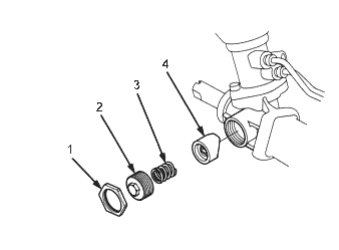
- 1. LOCK NUT
- 2. RACK GUIDE SCREW
- 3. SPRING
- 4. RACK GUIDE
- 7.Remove the spring and the rack guide from the gearbox.
PDF p. 835 · 17-40
- 8.Hold the steering gearbox in a vice with soft jaws. Be careful not to damage the housing with the jaws of the vice.
- 9.Remove the pinion shaft grommet, return hose joint, cylinder lines A and B from the gearbox.
- 10.Drain the fluid from the cylinder fittings by slowly moving the steering rack back and forth.
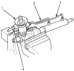
- 1. PINION SHAFT GROMMET
- 2. CYLINDER LINE A
- 3. CYLINDER LINE B
- 4. RETURN HOSE JOINT
- 11.Remove the valve body unit from the gearbox. For valve body unit disassembly (See Page 17-36 .)
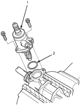
- 1. VALVE BODY UNIT
- 2. SHIMS
- 12.Drill a 3 mm (0.12 in) diameter hole approximately 2.5 - 3.0 mm (0.10-0.12 in) in depth in the staked point on the cylinder. Do not allow metal shavings to enter the cylinder housing. After removing the cylinder end, remove any burrs at the stake point.
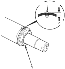
- 1. STAKED POINT
- 2. Depth 2.5-3.0 mm (0.10-0.12 in)
- 3. CYLINDER END
- 13.Loosen and remove the cylinder end.
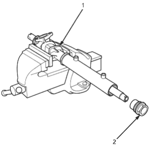
- 1. STEERING GEARBOX
- 2. CYLINDER END, Replace
PDF p. 836 · 17-41
- 14.Place a depth socket wrench on the steering rack.
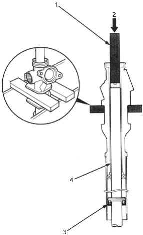
- 1. DEPTH SOCKET WRENCH
- 2. PRESS
- 3. CYLINDER END SEAL, Replace
- 4. STEERING RACK
- 15.Set the steering gearbox in a press so the driver’s side points upward, then press the cylinder end seal and steering rack out of the gearbox. Hold the steering rack to keep it from falling when pressed clear. Be careful not to damage the inner surface of the cylinder housing with the tool.
- 16.Remove the cylinder end seal from the steering rack.
- 17.Insert the special tools into the cylinder. Make sure that the special tool is securely positioned on the backup ring edges. Be careful not to damage the inner surface of the cylinder with the special tool.
- 18.
Set the gearbox in a press, then press out the cylinder and seal and backup ring from the gearbox.
Note these items when pressing the cylinder end seal:
- Keep the tool straight to avoid damaging the cylinder wall. Check the tool angel, and correct it if necessary, when removing the cylinder end seal.
- Use a press to remove the cylinder end seal. Do not try to remove the seal by striking the tool. It will break the backup ring, and the cylinder end seal will remain in the gearbox.
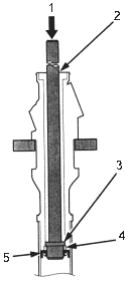
- 1. Press
- 2. DRIVER HANDLE, 07NAD-SR30101
- 3. END PACKING REMOVER, 07NAD-SR30200
- 4. BACKUP RING, Replace
- 5. CYLINDER END SEAL, Replace
PDF p. 837 · 17-42
- 19.Carefully pry the piston seal ring and O-ring off the piston rack. Be careful not to damage the inside of seal ring groove and piston edges when removing the seal ring.
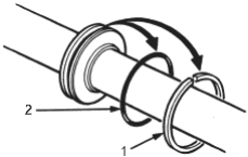
1. PISTON SEAL RING, Replace
- 2.O-RING, Replace
Valve Body Unit Disassembly
- 20.Before removing the valve housing, apply vinyl tape to splines of the pinion shaft.
- 21.Separate the valve housing from the pinion shaft/valve using a press
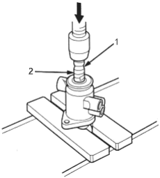
- 1. Vinyl tape
- 2. PINION SHAFT
- 22.
Check the inner wall of the valve housing where the seal ring slides with your finger. If there is a step in the wall, the valve housing is worn. Replace the valve housing.
NOTE:
- There may be the sliding marks from the seal ring on the wall of the valve housing. Replace the vale housing only if the wall is stepped.
- When the valve housing is replaced, install new shim(s) on the bearing surface of the housing to adjust the thickness
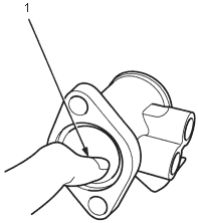
- 1. Check the inside of valve housing whether the wall is stepped.
PDF p. 838 · 17-43
- 23.
Check for wear, burrs and other damage to the edges of the grooves in the sleeve.
NOTE: the pinion shaft and sleeve are a precision matched set. If either pinion shaft or sleeve must be replaced, Replace both parts as a set.
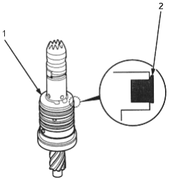
- 1. SLEEVE, Check for damage
- 2. SLEEVE SEAL RINGS, Check for peel off or damage
- 24.Remove the circlip and pinion shaft sleeve from the pinion shaft.
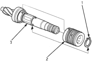
- 1. CIRCLIP, Replace
- 2. SLEEVE
- 3. PINION SHAFT
- 25.Using a cutter or an equivalent tool, cut and remove the four seal rings from the sleeve. Be careful not to damage the edges of the sleeve grooves and outer surface when removing the seal rings.
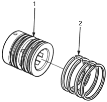
- 1. SLEEVE
- 2. SLEEVE SEAL RINGS, Replace
- 26.Using a cutter or an equivalent tool, cut the valve seal ring and O-ring at the groove on the pinion shaft. Remove the valve seal ring and O-ring. Be careful not to damage the edges of the pinion shaft groove and outer surface when removing the valve seal ring and O-ring.
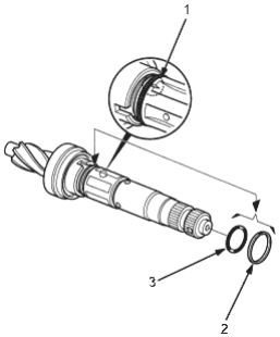
- 1. Cutting slot position
- 2. VALVE SEAL RING, Replace
- 3. O-RING, Replace
PDF p. 839 · 17-44
- 27.
Remove the valve oil seal and backup ring from the pinion shaft.
Note these items during disassembly:
- Inspect the ball bearing by rotating the outer race slowly. If there is any excessive play, replace the pinion shaft and sleeve as an assembly.
- The pinion shaft and sleeve are a precise fit; do not intermix old and new pinion shafts and sleeves.
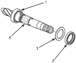
- 1. CIRCLIP, Replace
- 2. BALL BEARING
- 3. PINION SHAFT
- 4. BACK-UP RING
- 5. VALVE OIL SEAL, Replace
- 6. Press
- 28.Press the valve oil seal and ball bearing out of the valve housing using a hydraulic press and special tool shown below.
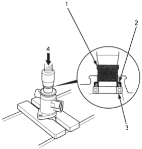
- 1. END PACKING REMOVER, 07NAD-SR30200
- 2. VALVE OIL SEAL, Replace
- 3. BALL BEARING, Replace
- 4. Press
PDF p. 840 · 17-45
Reassembly
Note these items during reassembly:
- Clean the disassembled parts with a solvent, and dry them with compressed air. Do not dip the rubber parts in a solvent.
- Always replace the O-rings and rubber seals with new ones before assembly.
- Apply power steering fluid or steering grease (HONDA P/N: 08733-B070E) to the parts indicated in the assembly procedures.
- Do not allow dust, dirt or other foreign materials to enter the power steering system.
- Use the appropriate special tools where necessary.
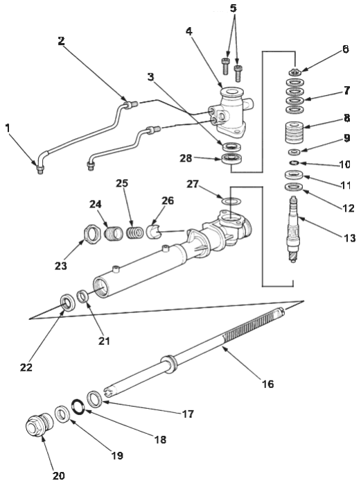
- 1. 24 Nm (2.4 kgf/m, 17 lbf/ft)
- 2. 20 Nm (2.0 kgf/m, 14 lbf/ft)
- 3. VALVE OIL SEAL, Replace
- 4. VALVE HOUSING
- 5. 25 Nm (2.5 kgf/m, 18 lbf/ft)
- 6. CIRCLIP, Replace
- 7. SLEEVE SEAL RINGS, Replace
- 8. SLEEVE
- 9. VALVE SEAL RING, Replace
- 10. O-RING, Replace
- 11. VALVE OIL SEAL, Replace
- 12. BACKUP RING
- 13. PINION SHAFT
- 14. BALL BEARING
- 15. CIRCLIP, Replace
- 16. STEERING RACK ♦
- 17. PISTON SEAL RING, Replace
- 18. O-RING, Replace
- 19. CYLINDER END SEAL, Replace
- 20. CYLINDER END, 69 Nm (7.0 kgf/m, 51 lbf/ft), Replace
- 21. BACKUP RING, Replace
- 22. CYLINDER END SEAL, Replace
- 23. LOCKNUT
- 24. RACK GUIDE SCREW
- 25. SPRING
- 26. RACK GUIDE
- 27. SHIMS
- 28. BALL BEARING
PDF p. 841 · 17-46
Valve Body Unit Reassembly
- 1.Apply grease to the ball bearing and install it on the pinion shaft using a hydraulic press. Then install the new circlip securely in the pinion shaft groove.
- 2.Apply vinyl tape to the stepped portion of the pinion shaft, and coat the surface of the vinyl tape with the power steering fluid. Install the backup ring.
- 3.Coat the inside surface of the new valve oil seal with power steering fluid.
- 4.Slide the valve oil seal over the pinion shaft, being careful not to damage the sealing lip. Install the valve oil seal with its grooved side facing opposite the bearing.
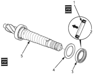
- 1. CIRCLIP, Replace
- 2. PINION SHAFT, Vinyl tape (Stepped portion)
- 3. Sealing lip
- 4. Groove side
- 5. VALVE OIL SEAL, Replace
- 6. BACKUP RING
- 7. NOTE: Support the inner race with the tool securely.
- 8. Press
- 9. BALL BEARING
- 5.Apply vinyl tape to the splines and stepped portion of the shaft, and coat the surface of the vinyl tape with the power steering fluid.
- 6.Fit the new O-ring in the groove of the pinion shaft. Then slide the new valve seal ring over the shaft and the groove in on the pinion shaft.
- 7.Remove the vinyl tape from the pinion shaft.
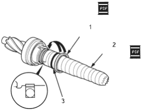
- 1. VALVE SEAL RING, Replace. Do not over expand.
- 2. Vinyl tape
- 3. O-RING, Replace. Do not twist.
- 8.Apply power steering fluid to the surface of the valve seal ring that was installed on the pinion shaft.
- 9.Apply power steering fluid to the inside of the special tool. Set the larger diameter end of the special tool over the valve seal ring.
- 10.Move the special tool up and down several times to make the valve seal ring fit in the pinion shaft.
- 11.Remove the special tool.
- 12.Turn the special tool over, and set the smaller diameter end of the special tool over the valve seal ring.
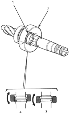
- 1. VALVE SEAL RING
- 2. VALVE SEAL RING SIZING TOOL, 07NAG-SR30900
- 3. Make the valve seal ring fit snugly in the pinion shaft using the other end (smaller diameter end) of the special tool.
- 4. Use the larger diameter end of the special tool first to make the valve seal ring fit in the pinion shaft.
PDF p. 842 · 17-47
- 13.
Apply power steering fluid to the surface of the special tool. Set the new seal rings over the special tool from the smaller diameter end of the tool, and expand the seal rings.
Note these items when installing seal ring:
- Do not over-expand the seal ring. Install the resin seal rings with care so as not to damage them. After installation, be sure to contract the seal rings using the special tool (sizing tool).
- There are two types of sleeve seal rings: black and brown. Do not mix the different types of sleeve seal rings as they are not compatible.
- 14.Align the special tool with each groove in the sleeve, and slide a sleeve seal ring in each groove securely. After installation, compress the seal rings with your fingers temporarily.
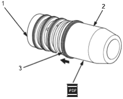
- 1. SLEEVE
- 2. SLEEVE SEAL GUIDE, 07NAG-SR30700
- 3. SLEEVE SEAL RING, Replace
- 15.Apply power steering fluid to the seal rings on the sleeve, and to the entire inside surface of the special tool.
- 16.Insert the sleeve into the special tool slowly.
- 17.
Move the sleeve each direction several times to make the seal rings snugly fit in the sleeve.
NOTE: Be sure that the seal rings are not turned up.
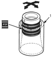
- 1. SLEEVE SEAL RING SIZING TOOL, 07NAG-SR30600
- 18.Apply power steering fluid to the surface of the pinion shaft. Assembly the sleeve over the pinion shaft by aligning the locating pin on the inside of the sleeve with the cutout in the shaft. Then install the new circlip securely in the pinion shaft groove. Be careful not to damage the valve seal ring when inserting the sleeve.
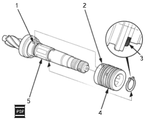
- 1. Cutout
- 2. LOCATING PIN
3 CIRCLIP
- 4.SLEEVE
- 5.PINION SHAFT
- 19.Apply power steering fluid to the seal ring lip of the valve oil seal, then install the seal in the valve housing using a hydraulic press and special tools as shown. Install the valve oil seal with its grooved side facing the tool.
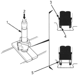
- 1. DRIVER, 07749-0010000,
- 2. Press
- 3. ATTACHMENT, 32 x 35 mm, 07746-0010100
- 4. VALVE OIL SEAL, Replace
- 5. BALL BEARING
- 20.Press the new bearing into the valve housing using a hydraulic press and special tool as shown.
PDF p. 843 · 17-48
Disassembly
- 21.Apply vinyl tape to the pinion shaft, then coat the vinyl tape with power steering fluid.
- 22.Insert the pinion shaft into the valve housing. Be careful not to damage the valve seal rings.
- 23.Remove the vinyl tape from the pinion shaft, then remove any residue from the tape adhesive.
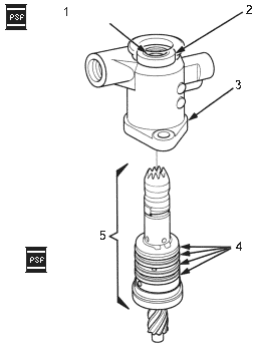
- 1. Sealing lip face.
- 2. VALVE OIL SEAL
- 3. VALVE HOUSING
- 4. SLEEVE SEAL RINGS
Replace. Be sure that the seal rings are not turned up, then install. - 5. PINION SHAFT
- 24.Press the pinion shaft/sleeve using a hydraulic press and special tool. Check that the pinion shaft/sleeve turns smoothly by turning the pinion shaft.
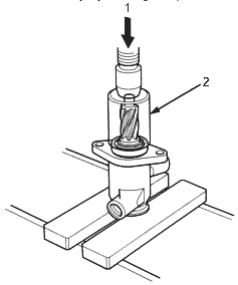
- 1. Press
- 2. HUB DIS/ASSEMBLY TOOL ATTACHMENT, 07965-SA50500
Steering Rack Reassembly
- 25.Coat the piston seal ring guide with power steering fluid, then slide it onto the rack, big end first.
- 26.
Position the new O-ring and new piston seal ring on the special tool, then slide them down toward the big end of the tool.
Note these items during reassembly:
- Do not over expand the resin seal rings. Install the resin seal rings with care so as not to damage them. After installation, be sure to contract the seal ring using the special tool (sizing tool).
- Replace the piston’s O-ring and seal ring as a set.
- 27.Pull the O-ring off into the piston groove, then pull the piston seal ring off into the piston groove on top of the O-ring.
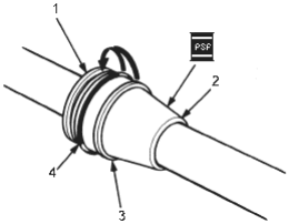
- 1. PISTON
- 2. PISTON SEAL RING GUIDE, 07NAG-SR30400
3. PISTON SEAL RING, Replace
- 4.O-RING, Replace
- 28.Coat the piston seal ring and the inside of the special tool with power steering fluid.
- 29.Carefully slide the tool onto the rack and over the piston seal ring.
- 30.Move the special tool back and forth several times to make the piston seal ring fit snugly in the piston.
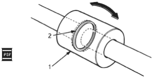
- 1. PISTON SEAL RING SIZING TOOL, 07NAG-SR30500
2. PISTON SEAL RING, Replace
PDF p. 844 · 17-49
Reassembly
- 31.
Wrap vinyl tape around the rack teeth and rack end edges, and coat the surface of the tape with the power steering fluid.
NOTE: Make sure that the vinyl tape is wrapped carefully so that there is no stepped portion.
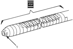
- 1. VINYL TAPE
- 32.Coat the inside surface of the new cylinder end seal with power steering fluid.
- 33.Install the cylinder end seal onto the steering rack with its grooved side toward the piston. When installing the cylinder end seal, be careful not to damage the sealing lip face of the seal with the edges or teeth of the steering rack.
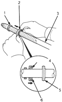
- 1. BACKUP RING, Replace.
- 2. CYLINDER END SEAL Replace.
- 3. STEERING RACK
- 4. Grooved side
- 5. PISTON
- 6. Make sure the spring is in the cylinder end seal.
- 34.Remove the vinyl tape from the steering rack, then remove nay residue of tape adhesive.
- 35.Install the new backup ring on the steering rack, then place the cylinder end seal to piston.
- 36.Grease the steering rack teeth, then insert the steering rack into the gearbox housing . Be careful not to damage the inner surface of the cylinder wall with the rack edges.
- 37.Insert an appropriate size depth socket wrench onto the steering rack as shown.
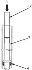
- 1. Press
- 2. SOCKET WRENCH
- 3. STEERING RACK
- 4. CYLINDER END SEAL, Replace
- 38.Install the cylinder end seal into the bottom of the cylinder by pressing on the tool with a press. Do not push on the tool with excessive force as it may damage the cylinder end seal.
- 39.Remove the depth socket wrench and centre the steering rack.
PDF p. 845 · 17-50
- 40.Wrap vinyl tape around the rack end edges, and coat the surface of the tape with the power steering fluid. Make sure that the vinyl tape is wrapped carefully so that there is no stepped portion.
- 41.Coat the inside surface of the new cylinder end seal with power steering fluid.
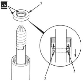
- 1. CYLINDER END SEAL, Replace
- 2. Grooved side.
- 3. Make sure the spring is in the cylinder end seal.
- 42.Install the cylinder end seal onto the steering rack with its grooved side toward the piston.
- 43.Push in the cylinder end seal with special tool. When installing the cylinder end seal, be careful not to damage the sealing face of the seal with the threads and burrs at the staked position of the cylinder housing.
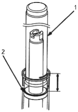
- 1. DRIVER, 30 mm I.D., 07946-MB00000
- 2. CYLINDER END SEAL
- 3. 60 mm (2.36 in.)
- 44.Remove the vinyl tape from the steering rack, then remove any residue from the tape adhesive.
- 45.Install the steering gearbox in a vise with soft jaws as shown. Do not clamp the cylinder in the vise.
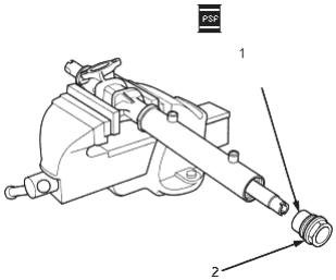
- 1. BUSHING
Be careful not to damage the bushing when inserting the cylinder end. - 2. CYLINDER END, 69 Nm (7.0 kgf/m, 51 lbf/ft)
- 46.Coat the inside surface of the cylinder end with power steering fluid, then install the cylinder end by screwing it into the cylinder.
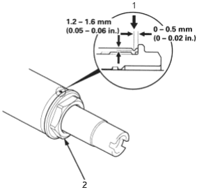
- 1. STAKED POINT
- 2. CYLINDER END
- 47.Remove the steering gearbox.
- 48.After tightening the cylinder end, stake the point of the cylinder shown. Stake the cylinder in the position opposite from where the stake was removed during disassembly.
PDF p. 846 · 17-51
- 49.Select the shim(s). Only reinstall the original shim(s) when the steering gearbox is reassembled without replacing the pinion shaft, valve housing, and gearbox housing with new ones.
Shim selection:
NOTE: Select number of the shims (7 shims, thickness: 0.05 mm/0.002 in.) before installing the valve body unit on the gear housing.
- A.Measure the depth “h” form the mating surface of the gear housing to the shim installation surface.
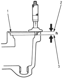
- 1. GEAR HOUSING
- 2. MATING FACE WITH VALVE BODY UNIT
- 3. SHIM INSTALLATION SURFACE
- B.Measure the height “h” from the mating surface of the valve body unit to the bearing end.
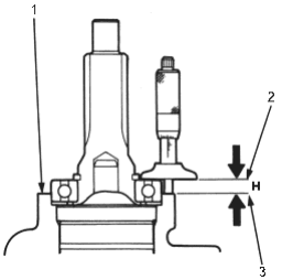
- 1. VALVE BODY UNIT
- 2. BEARING END
- 3. MATING FACE WITH GEAR HOUSING
- C.Select number of the shims so that the difference between the measurements “h” and “H” is 0.05 mm (0.002 in.) or below.
- 50.Set the selected shims on the bearing surface of the gearbox housing.
- 51.Apply grease to the needle bearing in the gearbox housing.
- 52.Be sure to apply the liquid gasket to the mating face evenly not to let it to drop inside the housing.
- 53.Install the valve body unit on the gearbox housing by engaging the gears. Note the valve body unit installation position (direction of line connection).
- 54.Tighten the bolts to the specified torque.
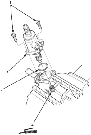
- 1. 25 Nm (2.5 kgf/m, 18 lbft)
- 2. VALVE BODY UNIT
- 3. SHIMS (Selected number of shims)
- 4. NEEDLE BEARING
PDF p. 847 · 17-52
- 55.
Install the return hose joint, cylinder lines A and B.
Note these items during reassembly:
- Clean the joints thoroughly. The joints must be free of foreign material.
- Install the cylinder lines A and B by tightening the flare nuts by hand first, then tighten the flare nuts to the specified torque.
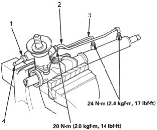
- 1. 16 mm FLARE NUT, 28 Nm (2.9 kgf/m, 21 lbf/ft)
- 2. CYLINDER LINE B
- 3. CYLINDER LINE A
- 4. RETURN HOSE JOINT
- 56.Install the pinion shaft grommet
- 57.Grease the sliding surface of the rack guide, and install it onto the gearbox housing.
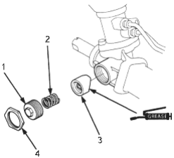
- 1. RACK GUIDE SCREW
- 2. SPRING
- 3. RACK GUIDE
- 4. LOCKNUT
- 58.Apply new sealant to all around threads on the rack guide screw.
- 59.Install the spring, rack guide screw and locknut on the gearbox.
- 60.Adjust the rack guide screw (See Page 17-17). After adjusting, check that the rack moves smoothly by sliding the rack right and left.
- 61.Install the lock washer, and screw each rack end into the rack while holding the lock washer so its tabs are in the slots in the end of the rack.
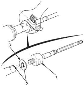
- 1. STEERING RACK END, 78 Nm (8.0 kgf/m, 58 lbf/ft)
- 2. Align
- 3. LOCK WASHER, Replace
- 62.Tighten the both rack ends. Be careful not to damage the rack surface with the wrench.
- 63.Bend the lock washer back against the flat spots on the rack end joint housing.
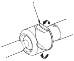
- 1. LOCK WASHER
PDF p. 848 · 17-53
- 64.Apply a light coat of silicone grease to the contact portions of the rack grooves and boot.
- 65.Centre the steering rack within its stroke. Apply weatherstrip adhesive to the in side of the boot and the boot fitting around of the cylinder housing. Install the boot in the rack end, and fit the boot over the cylinder housing. Install the tie-rod clip. After installing the boots, wipe the grease of the threaded section of rack end.
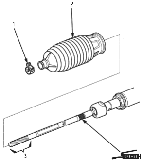
- 1. TIE-ROD CLIP
- 2. BOOT
- 3. NOTE: Wipe grease off the thread section
- 66.Install the new boot band by aligning the tabs with the holes of the band.
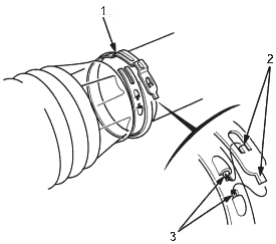
- 1. BOOT BAND, Replace
- 2. TABS
- 3. HOLES
NOTE: The ear portions of the band (close point) should be the specified angle shown below
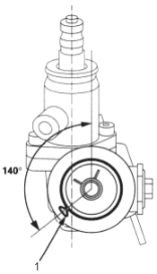
- 1. EAR PORTION, (Close point)
- 67.Close the ear portion of the band with a commercially available Oetiker 1098 pincer or equivalent.
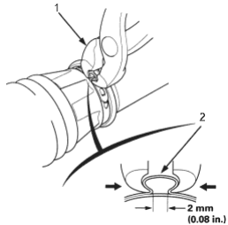
- 1. PINCER, (Commercially available)
- 2. EAR PORTION
- 68.Slide the rack right and left to be certain that the boots are not deformed or twisted.
- 69.Install the steering gearbox (See Page 17-54).
PDF p. 849 · 17-54
Installation
- 1.Install the steering gearbox mounting cushions and brackets on the steering gearbox as shown. Position the mounting cushion B so that the dimension between the mounting bracket A and B.
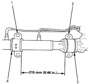
- 1. MOUNTING BRACKET B
- 2. MOUNTING BRACKET A
- 3. MOUNTING CUSHION A
- 4. MOUNTING CUSHION B
- 2.Before installing the gearbox, slide the rack all the way to the passenger’s side.
- 3.Install the pinion shaft grommet
- 4.Insert the steering gearbox into the engine compartment through the hole in the frame of the passenger’s side. Put on the gearbox installation position at the bulkhead. Be care not to bend or damage the power steering lines and cylinder lines when install the gearbox.
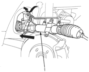
- 1. STEERING GEARBOX
- 5.Install the 10 mm gearbox mounting bolts on the gearbox driver’s side. The mounting bolts are loosely firs, then tighten them securely.
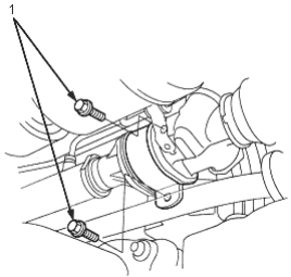
- 1. GEARBOX MOUNTING BOLTS, 44 Nm (4.5 kgf/m, 33 lbf/ft)
- 6.Install the 10 mm gearbox mounting bolts on the gearbox passenger’s side. The mounting bolts are loosely first, then tighten them securely.
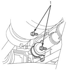
- 1. GEARBOX MOUNTING BOLTS, 44 Nm (4.5 kgf/m, 33 lbf/ft)
PDF p. 850 · 17-55
- 7.
Insert the stabiliser spring into the engine compartment through the hole in the frame of the passenger’s side.
NOTE: Do not interchange the stabiliser spring installation direction.
- 8.Tilt the stabiliser spring aslant that you inserted in the previous step, and turn it to pass the stabiliser end of the driver’s side through the hole in the frame of the driver’s side.
- 9.Lower the lower arm to bring the both stabiliser ends above the lower arms.
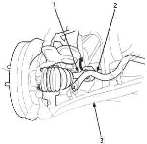
- 1. DRIVESHAFT
- 2. STABILISER SPRING
- 3. LOWER ARM
- 10.
Swing the knuckle forward. Turn the stabiliser spring to bring the stabiliser and above the drive shaft.
Bring the stabiliser spring of the opposite side above the driveshaft, too.
- 11.
Install the right and left stabilizer holders on the respective bushings and loosely tighten the mounting bolts.
NOTE: After installing the gearbox, tighten the bolts to the specified torque while applying the vehicle weight to the stabilizer.
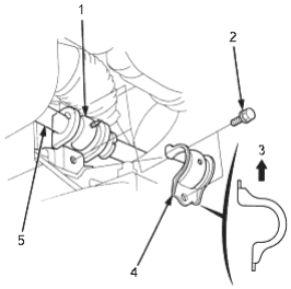
- 1. STABILIZER BUSHING
- 2. MOUNTING BOLTS, 22 Nm (2.2 kgf/m, 16 lbf/ft)
- 3. Upper side
- 4. STABILIZER HOLDER
- 5. STABILIZER SPRING
- 12.Connect the right and left lower arms to the knuckles. (see section 18).
- 13.
Connect the right and left stabilizer spring to the stabilizer link.
NOTE: After installing the gearbox, perform the following operation while applying the vehicle weight to the stabilizer spring.
- Set the ball joint pin of the stabilizer link in the center of the movable range of the joint, and reconnect it to the stabilizer spring.
- Tighten the bolts to the specified torque while holding the ball joint pin with a hex wrench.
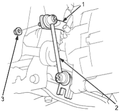
- 1. STABILISER SPRING
- 2. STABILISER LINK
- 3. 10 mm SELF-LOCK NUT, Replace, 38 Nm (3.9 kgf/m, 28 lbf/ft)
PDF p. 851 · 17-56
- 14.Connect the return hose securely, and tighten the adjustable hose clamp.
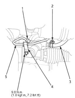
- 1. 14 mm FLARE NUT, 37 Nm (3.8 kgf/m, 27 lbf/ft)
- 2. ADJUSTABLE HOSE CLAMP
NOTE: For the hose clamps installation refer to(See Page 17-28). - 3. RETURN HOSE
- 4. SUPPLY LINE CLAMP
- 5. SUPPLY LINE
- 15.
Connect the supply line and tighten the 14 mm flare nut. Install the supply line clamp on the gearbox. For vehicles with RHD; install the supply line clamp on the mounting bracket.
NOTE: Make sure that there is no interference between the fluid lines and any other parts.
- 16.Connect the shift cable (CVT only) to the transmission.
- 17.Centre the steering rack within its stroke.
- 18.Install the steering joint, and reconnect the steering shaft and pinion shaft.
- Make sure the steering joint is connected as follows:
- Insert the upper end of the steering joint onto the steering shaft (line up the bolt hole with the flat portion on the shaft).
- Slip the lower end of the steering joint onto the pinion shaft (line up the bolt hole with the groove around the shaft), and tighten the lower bolt. Be sure that the lower steering joint bolt is securely in the groove in the pinion shaft.
- Pull on the steering joint to make sure that the steering joint is fully seated. Then install the upper joint bolt and tighten it.
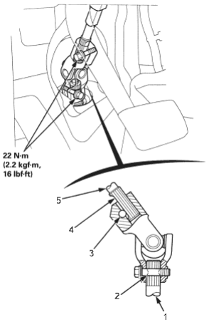
- 1. PINION SHAFT
- 2. Groove
- 3. Bolt hole
- 4. Flat portion
- 5. STEERING SHAFT
- 19.
Centre the cable reel by first rotating it clockwise until it stops. Then rotate it counterclockwise (approximately two and half turns) until the arrow mark on the label points straight up.
Reinstall the steering wheel (See Page 17-22).
PDF p. 852 · 17-57
- 20.Install the steering joint cover.
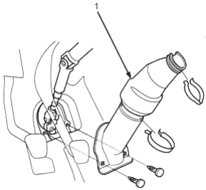
- 1. STEERING JOINT COVER
- 21.Wipe off any grease contamination from the ball joint tapered section and threads. Reconnect the tie-rod ends to the steering knuckles. Install the 12 mm nut and tighten to the specified torque.
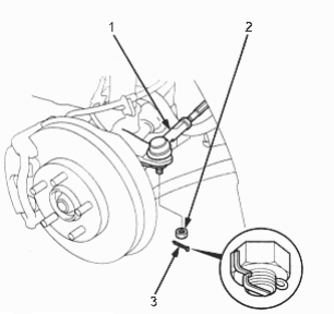
- 1. TIE-ROD END
- 2. 12 mm NUT
43 Nm (4.4 kgf/m, 3.2 lbf/ft) - 3. COTTER PIN, Replace
On reassembly, bend the cotter pin as shown
- 22.Install the front wheels.
- 23.Fill the system with power steering fluid, and bleed air from the system (See Page 17-18).
- 24.After installation, perform the following checks.
- Start the engine, allow it to idle, and turn the steering wheel from lock -to-lock several times to warm up the fluid. Check the gearbox for leaks (See Page 17-27).
- Adjust the front toe (see section 18).
- Check the steering wheel spoke angle. Adjust by turning the right and left tie-rods, if necessary.
NOTE: Turn the right and left tie-rods equally.
PDF p. 853 · 17-58
Ball Joint Boot Replacement
- 1.Remove the boot from the tie-rod end, and wipe the old grease off the ball pin.
- 2.Pack the lower area of the ball pin with fresh grease.
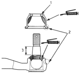
- 1. LIP
- 2. BOOT INSTALLATION SECTION, Wipe off the grease.
- 3. BALL PIN TAPERED SECTION, Wipe off the grease.
- 3.
Pack the interior of the new boot and lip with fresh grease.
Note these items when installing new grease:
- Keep grease off the boot installation section and the tapered section of the ball pin’
- Do not allow dust, dirt, or other foreign materials to enter the boot.
- 4.Install the new boot using the special tool. The boot must not have a gap at the boot installation sections. After installing the boot, check the ball pin tapered section for grease contamination, and wipe it if necessary.
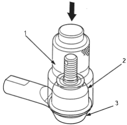
- 1. OIL SEAL DRIVER, 07974-6790000
- 2. BOOT
- 3. TIE-ROD END