PDF p. 823 · 17-28
Note these times during installation:
- Connect each hose to the corresponding line securely until it contacts the stop on the line,. Install the clamp or adjustable clamp at the specified distance from the hose end as shown.
- Check all clamps for deterioration or deformation; replace with new clamps if necessary.
- Add the recommended power steering fluid to the specified level on the reservoir and check for leaks.
ADJUSTABLE HOSE CLAMP: (A)
- Position the adjustable hose clamps at the three points indicated.
- Slide the hose over the line until it contacts the stop.
HOSE CLAMP; (B)
- Position the hose clamps at the four point indicated.
- Slide the hose over the line until it contacts the stop.
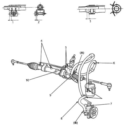
- 1. 2.5-5.5 mm (0.1-0.2 in.)
- 2. 2.0-4.0 mm (0.08-0.16 in.)
- 3. 2.5-5.5 mm (0.1-0.2 in.)
- 4. CYLINDER LINE-to-CYLINDER
24 Nm (2.4 KGF/M, 17 LBF/FT) - 5. cylinder line -to-VALVE BODY UNIT 20 Nm (2.0 kgf/m, 14 lbf/ft)
- 6. RETURN HOSE
- 7. SUPPLY LINE to PUMP 6 x 1.0 mm 11 Nm (1.1 kgf/m, 8 lbf/ft)
- 8. INLET HOSE
- 9. RETURN LINE JOINT
16 x 1.5 mm
28 Nm (2.9 kgf/m, 21 lbf/ft) - 10. SUPPLY LINE 14 x 1.5 mm
37 Nm (3.8 kgf/m. 27 lbf/ft)