PDF p. 818 · 17-23
SRS components are located in this area. Review the SRS component locations, precautions, and procedures in the SRS section (24) before performing repairs or service.
- 1.Remove the driver’s airbag assembly and cable reel (see section 24).
- 2.Remove the steering wheel (See page 17-20).
- 3.Remove the driver’s dashboard lower cover (see section 20).
- 4.Remove the column covers.
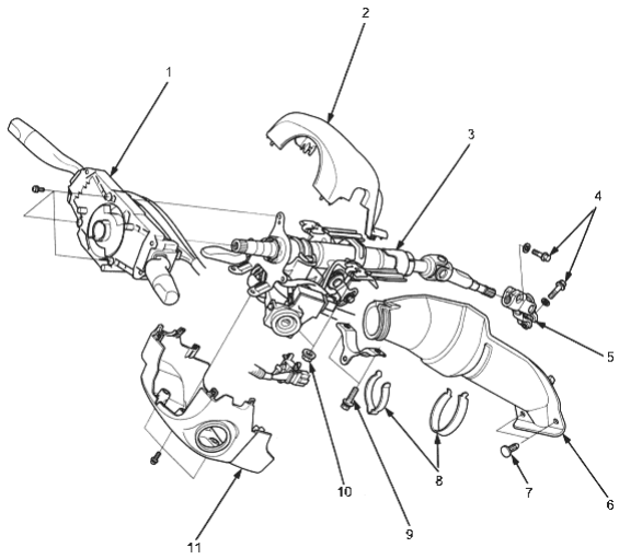
- 1. COMBINATION SWITCH
- 2. UPPER COLUMN COVER
- 3. STEERING COLUMN
- 4. 22 Nm (2.2 kgf/m, 16 lbf/ft)
- 5. STEERING JOINT
- 6. STEERING JOINT COVER
- 7. CLIPS
- 8. CLAMPS
- 9. 22 Nm (2.2 kgf/m, 16 lbf/ft)
- 10. 13 Nm (1.3 kgf/m, 9.4 lbf/ft)
- 11. LOWER COLUMN COVER
- 5.Remove the combination switch assembly from the steering column shaft by disconnecting the connectors.
- 6.Disconnect the ignition switch connectors.
- 7.Remove the steering joint cover.
- 8.Disconnect the steering joint, and remove it from the column shaft.
- 9.Remove the steering column by removing the attaching nuts and bolts.
PDF p. 819 · 17-24
- 10.
Install the steering column in the reverse of removal,
and note these items:
- Be sure the wires are not caught or pinched by any parts when installing the column.
- Make sure the wire harness is routed and fastened properly.
- Make sure the connectors are properly connected.
- Make sure the steering joint is connected as follows:
- Insert the upper end of the steering joint onto the steering shaft (line up the bolt hole with the flat portion on the shaft).
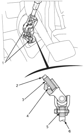
- 1. 22 N (2.2 kgf/m, 16 lbf/ft)
- 2. STEERING SHAFT
- 3. Flat portion
- 4. Bolt hole
- 5. Groove
- 6. PINION SHAFT
- Slip the lower end of the steering joint onto the pinion shaft (line up the bolt hole with the groove around the shaft), and install the lower joint bolt and tighten it. Be sure that the lower joint bolt is securely in the groove in the pinion shaft.
- Put on the steering joint to make sure that the steering joint is fully seated. Then install the upper joint bolt and tighten it.