PDF p. 812 · 17-17
- 1.Remove the rear beam.
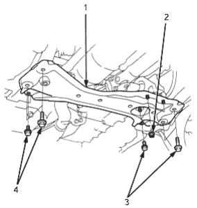
- 1. REAR BEAM
- 2. 39 Nm (4.0 kgf/m, 29 lbf/ft)
- 3. 64 Nm (6.5 kgf/m, 47 lbf/ft)
- 4. 64 Nm (6.5 kgf/m, 47 lbf/ft)
- 2.For vehicles with LHD; remove the floor heat baffle plate.
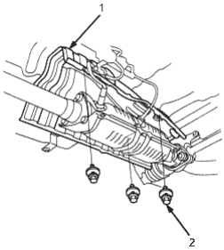
- 1. FLOOR HEAT BAFFLE PLATE
- 2. 9.8 Nm (1.0 kgf/m, 7.2 lbf/ft)
- 3.For vehicles with RHD; remove the shift cable clamp (CVT only). Remove the rear mounting bracket from the transmission housing.
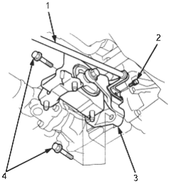
- 1. SHIFT CABLE (CVT)
- 2. 9.8 Nm (1.0 kgf/m 7.2 lbf/ft)
- 3. REAR MOUNTING BRACKET
- 4. 44 Nm (4.5 kgf/m, 33 lbf/ft)
- 4.Set the wheels in the straight ahead position.
- 5.Loosen the rack guide screw locknut with the special tool
- 6.Loosen the rack guide screw.
- 7.Tighten the rack guide screw to 5 Nm (0.5 kgf/m, 4 lbf/ft), then loosen it. Repeat twice.
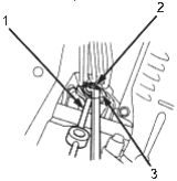
- 1. LOCKNUT WRENCH, 40 mm 07MAA-SL00100
- 2. RACK GUIDE SCREW
- 3. LOCKNUT, 67 Nm (6.8 kgf/m, 49 lbf/ft)
- 8.Retighten the rack guide screw to 5 Nm (0.5 kgf/m, 4 lbf/ft), then back it off to specified angle. Specified Angle: 10-15°
- 9.Tighten the locknut while holding the rack guide screw.
- 10.Check for tight or loose steering through the complete turning travel.
- 11.Installation of the removed parts are the reverse of the removal procedure.
- 12.Perform following inspections:
- Steering operation (See page 17-14).
- Power assist with vehicle parked (See Page 17-14).