PDF p. 776 · 16-17
Removal
- 1.Loosen the wheel nuts slightly.
- 2.Raise the rear of the vehicle and support it with safety stands in the proper location (see section 1).
- 3.Remove the wheel nuts and rear wheels.
- 4.Drain the rear differential oil (see section 15).
- 5.Remove the rear differential (see section 15).
- 6.Remove the rear hub bearing unit (see section 18).
- 7.Remove the two backing plate mounting bolts.
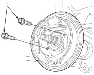
- 1. BACK PLATE MOUNTING BOLTS
- 8.Remove the rear driveshaft using the special tool as shown.
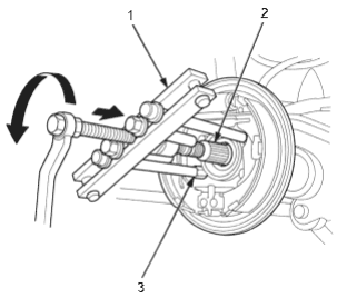
- 1. HUB PULLER, 07935-6790000
- 2. DRIVESHAFT
- 3. HUB PULLER ATTACHMENT, 07JAC-SJ60200
Disassembly
Inboard Joint Side:
- 1.Remove the set ring from the inboard joint.
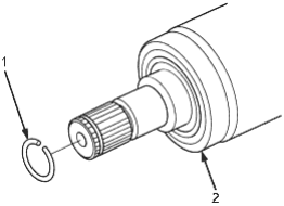
- 1. SET RING, Replace
- 2. INBOARD JOINT
- 2.Remove the boot bands. Take care not to damage the boot and dynamic damper.
- If the boot band is a welded type, cut the boot band.
- If the boot band is a double loop type, lift up the boot band.
Welded Type:
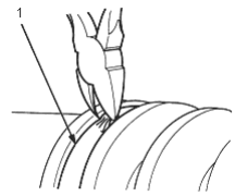
- 1. WELDED BAND, Replace
Double Loop Type:
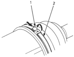
- 1. Band bend
- 2. DOUBLE LOOP BAND, Replace
PDF p. 777 · 16-18
- 3.Remove the snap ring from the inboard joint.
- 4.Place reference marks on the inboard joint and the bearing retainer as shown. Wrap the inboard joint with shop towel taking care not to drop the steel balls from the bearing retainer, then separate the inboard joint from the driveshaft.
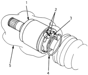
- 1. INBOARD JOINT
Check splines for wear or damage Check inside bore for wear Inspect for cracks - 2. Marks
- 3. BEARING RETAINER
- 4. SNAP RING
- 5. SHOP TOWEL
- 5.Place reference marks on the driveshaft, bearing race and the bearing retainer as shown.
- 6.Remove the steel ball from the bearing retainer. Take care not to damage the steel ball.
- 7.Remove the circlip.
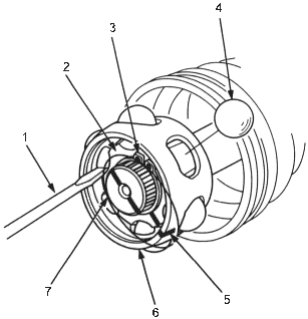
- 1. SCREWDRIVER
- 2. BEARING RACE
- 3. CIRCLIP
- 4. STEEL BALL
Check for wear or damage - 5. Mark
- 6. BEARING RETAINER
- 7. DRIVESHAFT
- 8.Remove the bearing race from the driveshaft using a commercially available bearing remover.
- 9.Remove the bearing retainer.
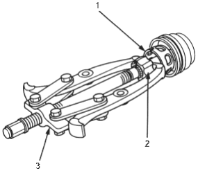
- 1. BEARING RETAINER Check for wear or damage
- 2. BEARING RACE
Check for wear or damage - 3. BEARING REMOVER (Commercially available)
- 10.Wrap the splines on the driveshaft with vinyl tape to prevent damage to the inboard boot.
- 11.Remove the inboard boot. Take care not to damage the boot.
- 12.Remove the vinyl tape.
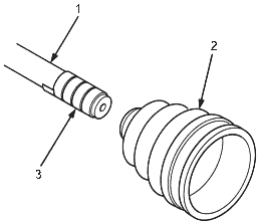
- 1. DRIVESHAFT
- 2. INBOARD BOOT
- 3. VINYL TAPE
PDF p. 778 · 16-19
Outboard Joint Side:
- 1.Remove the boot bands. Take care not to damage the boot and dynamic damper.
- If the boot band is welded type, cut the boot band.
- If the boot band is a double loop type, lift up the boot band.
Welded Type:
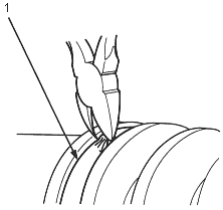
- 1. WELDED BAND, Replace
Double Loop Type:
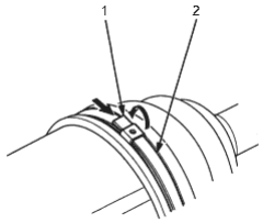
- 1. Band bend
- 2. DOUBLE LOOP BAND, Replace
- 2.Wipe off the grease to expose the driveshaft and the outboard joint inner race.
- 3.Make a mark on the driveshaft at the same position of the outboard joint end with paint.
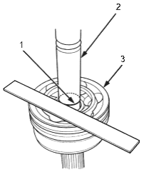
- 1. PAINT MARK
- 2. DRIVESHAFT
- 3. OUTBOARD JOINT END
- 4.Carefully clamp the driveshaft in a vice.
- 5.Remove the outboard joint using the special tools.
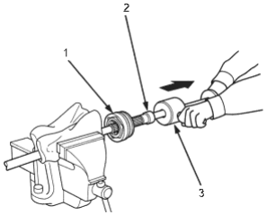
- 1. OUTBOARD JOINT
- 2. THREADED ADAPTER, 22 x 1.5 mm, 07XAC-0010100
- 3. SLIDING HAMMER SET, 07936-5790001
- 6.Remove the driveshaft from the vice.
PDF p. 779 · 16-20
- 7.Remove the stop ring from the driveshaft.
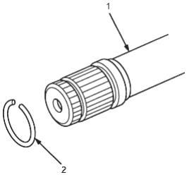
- 1. DRIVESHAFT
- 2. STOP RING, Replace
- 8.Wrap the splines on the driveshaft with vinyl tape to prevent damage to the outboard boot and dynamic damper.
- 9.Remove the outboard boot. Take care not to damage the boot.
- 10.Remove the vinyl tape.
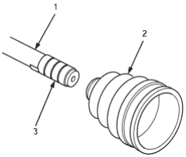
- 1. DRIVESHAFT
- 2. OUTBOARD BOOT
- 3. VINYL TAPE
PDF p. 780 · 16-21
Reassembly
Note the following items during reassembly:
- Clean the disassembled parts with solvent and dry them thoroughly with compressed air. Do not wash the rubber parts with solvent.
- Thoroughly pack both joints and both joint boots with the joint grease included in the new driveshaft set.
Grease quantity
Inboard joint: 45 - 65 g (1.6 - 2.3 oz)
Outboard joint: 30 -40 g (1.1 - 1.4 oz)
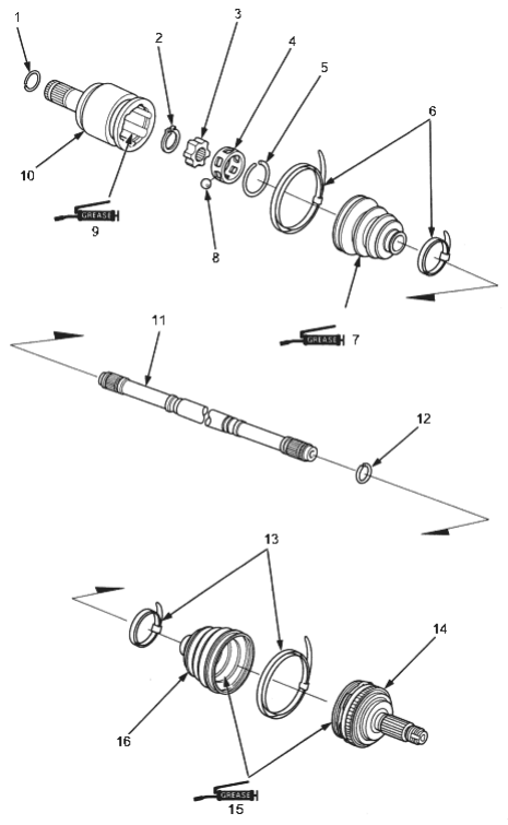
- 1. SET RING, Replace
- 2. CIRCLIP
- 3. BEARING RACE
- 4. BEARING RETAINER
- 5. SNAP RING
- 6. BOOT BANDS, Replace
- 7. INBOARD BOOT
Pack cavity with grease - 8. STEEL BALL
- 9. Pack cavity with grease
- 10. INBOARD JOINT
- 11. DRIVESHAFT
- 12. STOP RING, Replace
- 13. BOOT BANDS, Replace
- 14. OUTBOARD JOINT
- 15. Pack cavity with grease
- 16. OUTBOARD BOOT
PDF p. 781 · 16-22
Inboard Joint Side:
- 1.Wrap the splines with vinyl tape to prevent damage to the inboard boot.
- 2.Install the inboard boot to the driveshaft, then remove the vinyl tape. Take care not to damage the inboard boot.
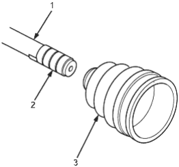
- 1. DRIVESHAFT
- 2. VINYL TAPE
- 3. INBOARD BOOT
- 3.Set the bearing retainer with its large bore side facing the end of the driveshaft, then install the bearing race on the driveshaft.
- 4.Align the reference mark on the bearing race with the mark on the drive shaft, then install the bearing race on the driveshaft.
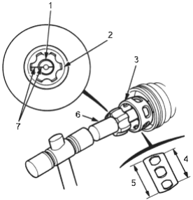
- 1. DRIVESHAFT
- 2. BEARING RACE
- 3. BEARING RETAINER
- 4. Small bore
- 5. Large bore
- 6. SOCKET
- 7. Marks
- 5.Fit the circlip into the driveshaft groove. Always rotate the circlip in its groove to be sure it is fully seated.
- 6.Position the bearing retainer on the bearing race with aligning the reference marks.
- 7.Install the steel balls into the bearing retainer holes.
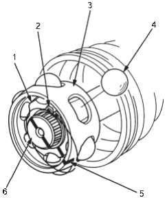
- 1. BEARING RACE
- 2. CIRCLIP
- 3. BEARING RETAINER
- 4. STEEL BALL
- 5. Mark
- 6. DRIVESHAFT
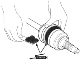
- 8.
Pack the inboard joint with the joint grease included in the new driveshaft set.
Grease quantity: 45 - 65 g (1.6 - 2.3 oz)
PDF p. 782 · 16-23
- 9.Install the inboard joint onto the driveshaft by aligning the marks on the inboard joint with the marks on the bearing retainer.
- 10.Install the snap ring into the inboard joint groove.
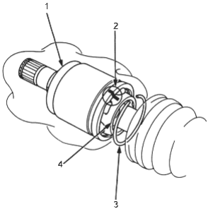
- 1. INBOARD JOINT
- 2. Mark
- 3. SNAP RING
- 4. BEARING RETAINER
- 11.
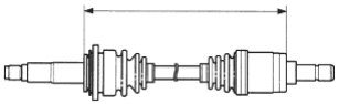
Adjust the length of the driveshafts to the figure below, then adjust the boots to halfway between full compression and full extension. Make sure the ends of the boots seat in the grooves of the driveshaft and joint.
Standard:
Left driveshaft: 558.3 mm (22.0 in)
Right driveshaft: 623.2 mm (24.5 in)
- 12.Fit the boot ends onto the driveshaft and the inboard joint, then install the boot bands with the band end towards the front of the vehicle.
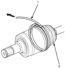
- 1. DOUBLE LOOP BAND, Replace
- 2. BOOT
- 13.Pull up the slack in the band by hand.
- 14.Mark a position on the band 10 -14 mm (0.4 - 0.6 in) from the clip.
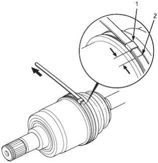
- 1. CLIP
- 2. Mark
PDF p. 783 · 16-24
- 15.Thread the free end of the band through the nose section of the commercially available boot band tool KD-3191 or equivalent and into the slot on the winding mandrel.
- 16.Place a wrench on the winding mandrel of the band tightening tool and tighten the band until the marked spot on the band meets the edge of the clip.
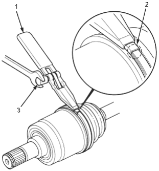
- 1. BAND TIGHTENING TOOL (Commercially available)
- 2. Mark spot
- 3. WINDING MANDREL
- 17.Lift up the band tightening tool to bend the free end of the band 90° to the clip. Centre punch the clip then fold over the remaining tail onto the clip.
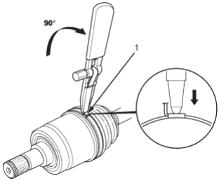
- 1. CLIP
- 18.Unwind the band tightening tool and cut off the excess free end of the band to leave a 5 - 10 mm (0.2 - 0.5 in) tail protruding from the clip.
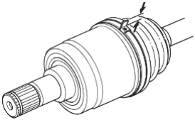
- 19.
Bend the band end by tapping it down with a hammer.
NOTE:
- Make sure the band and clip do not interfere with anything and the band does not move.
- Remove any grease remaining on the surrounding surfaces.
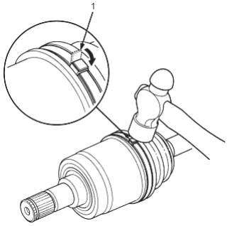
- 1. Band end
PDF p. 784 · 16-25
- 20.Install the new set ring.
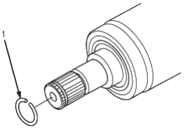
- 1. SET RING, Replace
Outboard Joint Side:
- 1.Wrap the splines with vinyl tape to prevent damage to the outboard boot.
- 2.Install the outboard boot. Take care not to damage the outboard boot.
- 3.Remove the vinyl tape.
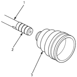
- 1. DRIVESHAFT
- 2. VINYL TAPE
- 3. OUTBOARD BOOT
- 4.Install the new stop ring into the driveshaft groove.
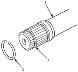
- 1. DRIVESHAFT
- 2. GROOVE
- 3. STOP RING, Replace
PDF p. 785 · 16-26
- 5.Insert the driveshaft into the outboard joint until the stop ring is close to the joint.
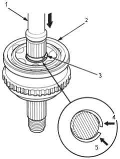
- 1. DRIVESHAFT
- 2. OUTBOARD JOINT
- 3. STOP RING
- 4. Push.
- 5. Push.
- 6.To completely seat the outboard joint, pick up the driveshaft and joint and drop them from about 10 cm (4 in) onto a hard surface. Do not use a hammer, as excessive force may damage the driveshaft.
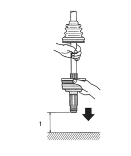
- 1. 10 cm 4 to 5 inches
- 7.Check the alignment of the paint mark with the outboard joint end.
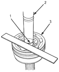
- 1. PAINT MARK
- 2. DRIVESHAFT
- 3. OUTBOARD JOINT END
- 8.
Pack the outboard joint with the joint grease included in the new joint boot set.
Grease quantity
Outboard joint: 30 - 40 g (1.1 - 1.4 oz)
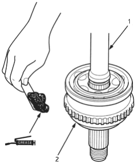
- 1. DRIVESHAFT
- 2. OUTBOARD JOINT
PDF p. 786 · 16-27
- 9.Fit the boot ends onto the driveshaft and outboard joint.
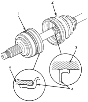
- 1. OUTBOARD JOINT
- 2. OUTBOARD BOOT
- 3. DRIVESHAFT
- 4. OUTBOARD BOOT
- 5. OUTBOARD JOINT
- 10.Set the boot bands with the band end towards the front of the vehicle.
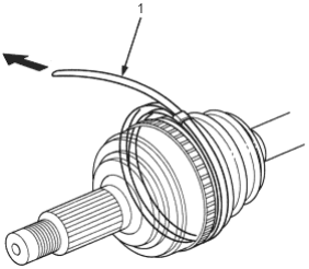
- 1. DOUBLE LOOP BAND, Replace
- 11.Pull up the slack in the band by hand.
- 12.Mark a position on the band 10 -14 mm (0.4 - 0.6 in) from the clip.
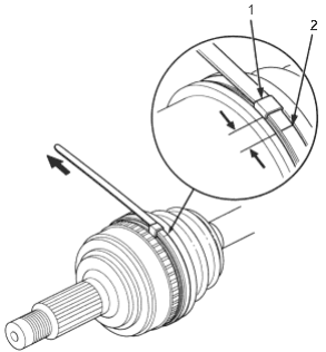
- 1. CLIP
- 2. Mark
- 13.Thread the free end of the band through the nose section of the commercially available boot band tool KD-3191 or equivalent and into the slot on the winding mandrel.
- 14.Place a wrench on the winding mandrel of the band tightening tool and tighten the band until the marked spot on the band meets the edge of the clip.
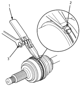
- 1. BAND TIGHTENING TOOL (Commercially available)
- 2. Mark spot
- 3. WINDING MANDREL
PDF p. 787 · 16-28
- 15.Lift up the band tightening tool to bend the free end of the band 90° to the clip. Centre punch the clip then fold over the remaining tail onto the clip.
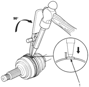
- 1. CLIP
- 16.Unwind the band tightening tool and cut off the excess free end of the band to leave a 5 - 10 mm (0.2 - 0.5 in) tail protruding from the clip.
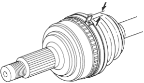
- 17.
Bend the band end by tapping it down with a hammer.
NOTE:
- Make sure the band and clip do not interfere with anything and the band does not move.
- Remove any grease remaining on the surrounding surfaces.
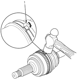
- 1. Band end
PDF p. 788 · 16-29
Installation
- 1.Install the set ring on the outboard joint.
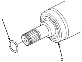
- 1. SET RING, Replace
- 2. INBOARD JOINT
- 2.Install the rear driveshaft using the special tool as shown.
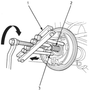
- 1. HUB PULLER, 07935-679000
- 2. DRIVESHAFT
- 3. HUB PULLER ATTACHMENT, 07JAC-SJ60200
- 3.Install the two backing plate mounting bolts.
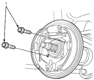
- 1. 10 x 1.25 mm, 64 Nm (6.5 kgf/m, 47 lbf/ft)
- 4.Install the rear hub bearing unit (see section 18).
- 5.Install the rear differential (see section 15).
- 6.Refill the rear differential oil (see section 15).
- 7.Install the wheel nuts and rear wheels.