PDF p. 629 · 14-74
SRS components are located in this area. Review the SRS component locations, precautions and procedures in the SRS (section 23) before performing repairs or service.
- 1.Remove the gauge assembly from the dashboard (see section 20), then disconnect the A (22P) and B (16P) connectors from the gauge assembly.
- 2.Inspect the connectors and connector terminals to be sure they are making good contact.
- 3.If the terminals are bent, loose or corroded, repair them as necessary and recheck the system.
- 4.Perform the following input test at the gauge assembly A (22P) and B (16P) connectors.
- 5.If all the input tests prove OK, but the indicator is faulty, replace the printed circuit board.
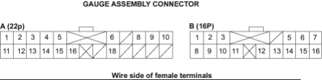
| Cavity | Wire Colour | Test Condition | Test: Desired Result | Possible Cause | |
|---|---|---|---|---|---|
| (if result is not obtained) | |||||
| A1 | GRN/BLK | Ignition switch ON (II) | Check for voltage to | ♦ | Faulty A/T gear position switch |
| and shift lever in D | ground: There should be | ♦ | Faulty PCM | ||
| battery voltage. | ♦ | An open in the wire | |||
| A2 | GRN/BLK | Ignition switch ON | Check for voltage to | ♦ | Faulty A/T gear position switch |
| (II), shift lever in D | ground: There should be | ♦ | Faulty S mode switch | ||
| and S mode switch is | battery voltage. | ♦ | Faulty PCM | ||
| turned on | ♦ | An open in the wire | |||
| A3 | BLU | Ignition switch ON (II) | Check for voltage to | ♦ | Faulty A/T gear position switch |
| and shift lever in 2 | ground: There should be 1 | ♦ | An open in the wire | ||
| V or less. | |||||
| NOTE: There should be | |||||
| battery voltage in any | |||||
| other shift lever position. | |||||
| A4 | LT GRN | Ignition switch ON (II) | Check for voltage to | ♦ | Faulty A/T gear position switch |
| and shift lever in N | ground: There should be 1 | ♦ | An open in the wire | ||
| V or less. | |||||
| NOTE: There should be | |||||
| battery voltage in any | |||||
| other shift lever position. | |||||
| A11 | BLK/BLU | Shift lever in P | Check for continuity to | ♦ | Faulty A/T gear position switch |
| ground: There should be | ♦ | An open in the wire | |||
| no continuity. | |||||
| A12 | WHT | Ignition switch ON (II) | Check for voltage to | ♦ | Faulty A/T gear position switch |
| and shift lever in R | ground: There should be 1 | ♦ | An open in the wire | ||
| V or less. | |||||
| NOTE: There should be | |||||
| battery voltage in any | |||||
| other shift lever position. | |||||
| A13 | RED | Ignition switch ON (II) | Check for voltage to | ♦ | Faulty A/T gear position switch |
| and shift lever in N | ground: There should be 1 | ♦ | An open in the wire | ||
| V or less. | |||||
| NOTE: There should be | |||||
| battery voltage in any | |||||
| other shift lever position. | |||||
| B13 | BLK | Under all conditions | Check for continuity to | ♦ | Poor ground (G401, 402) |
| ground: There should be | ♦ | An open in the wire | |||
| continuity. | |||||
| B15 | YEL | Ignition switch ON (II) | Check for voltage to | ♦ | Brown No. 6 (7.5 A) fuse in the |
| ground: There should be | under-dash fuse/relay box) | ||||
| battery voltage. | ♦ | An open in the wire |