PDF p. 625 · 14-70
- 1.Disconnect the drive pulley, the driven pulley, or the secondary gear shaft speed sensor connector.
- 2.Remove the 6 mm bolt from the transmission housing and remove the drive pulley, the driven pulley, or the secondary gear shaft speed sensor.
- 3.Replace the O-ring with a new one before reinstalling the drive pulley, the driven pulley, or the secondary gear shaft speed sensor.
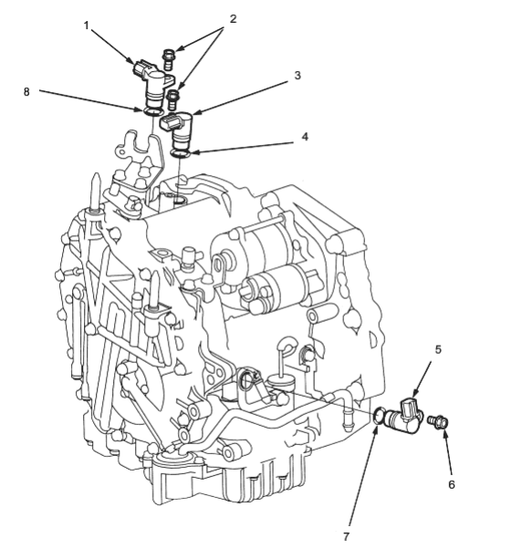
- 1. SECONDARY GEAR SHAFT SPEED SENSOR
- 2. 6 x 1.0 mm, 12 Nm (1.2 kgf/m, 8.7 lbf/ft)
- 3. DRIVEN PULLEY SPEED SENSOR
- 4. O-RING Replace.
- 5. DRIVE PULLEY SPEED SENSOR
- 6. 6 x 1.0 mm, 12 Nm (1.2 kgf/m, 8.7 lbf/ft)
- 7. O-RING Replace.
- 8. O-RING Replace.