PDF p. 624 · 14-69
- 1.Disconnect the 8P connector from the solenoid harness connector.
- 2.
Measure the resistance of the shift control linear solenoid between the No. 3 and No. 7 terminals of the solenoid harness connector.
STANDARD: 3.8 - 6.8 ohms
- 3.
Measure the resistance of the PH-PL control linear solenoid between the No. 2 and No. 6 terminals.
STANDARD: 3.8 - 6.8 ohms
- 4.
Measure the resistance of the start clutch control linear solenoid between the No. 4 and No. 8 terminals.
STANDARD: 3.8 - 6.8 ohms
- 5.
Measure the resistance of the inhibitor solenoid between the No. 5 terminal and body ground.
STANDARD: 11.7 - 21.0 ohms
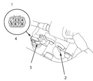
- 1. SOLENOID HARNESS CONNECTOR
- 2. ATF DIPSTICK
- 3. SOLENOID HARNESS CONNECTOR
- 4. Terminal side of male terminals
- 6.Replace the lower valve body assembly if any of the solenoids resistance is beyond the standard.
- 7.If all of the resistances are within the standard, a clicking sound should be heard when connecting the battery terminals to the solenoid harness connector terminals below:
Shift control linear solenoid
No. 3: Battery positive terminal
No. 7: Battery negative terminal
PH-PL control linear solenoid
No. 2: Battery positive terminal
No. 6: Battery negative terminal
Start clutch control linear solenoid
No. 4: Battery positive terminal
No. 8: Battery negative terminal
Inhibitor solenoid
No. 5: Battery positive terminal
Body ground: Battery negative terminal
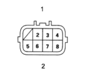
- 1. SOLENOID HARNESS CONNECTOR
- 2. Terminal side of male terminals
- 8.
If no clicking sound is heard, replace the lower valve body assembly.
NOTE: If the lower valve body assembly replacement is required, refer to Lower Valve Body Assembly Replacement (See Page 14-87).