PDF p. 719 · 14-162
- 1.Remove the used grease in the flywheel hub cap and flywheel splines.
- 2.Fill the inside of the flywheel hub cap and coat the flywheel hub splines with Super Urea Grease (P/N 08798-9002) as shown.
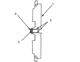
- 1. FLYWHEEL
- 2. SPLINES Apply SUPER HIGH TEMP UREA GREASE (P/N 08798-9002)
- 3. SUPER HIGH TEMP UREA GREASE (P/N 08798-9002) 1.5 - 2.5 g (0.05 - 0.09 oz)
- 4. FLYWHEEL HUB CAP
- 3.Install the new sealing ring (rubber) on the input shaft and install two 14 x 20 mm dowel pins in the flywheel housing.
- 4.Input the flywheel securely in the input shaft, then install the starter on the flywheel housing.
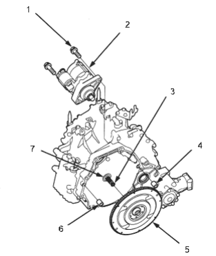
- 1. 44 Nm (4.5 kgf/m, 33 lbf/ft)
- 2. STARTER
- 3. SEALING RING (RUBBER)
- 4. 14 x 20 mm, DOWEL PIN
- 5. FLYWHEEL
- 6. 14 x 20 mm, DOWEL PIN
- 7. INPUT SHAFT
- 5.Place the transmission on a jack and raise it to the engine assembly level.
- 6.Attach the transmission on the engine, then install the transmission housing mounting bolt.
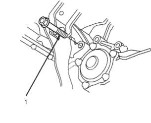
- 1. TRANSMISSION HOUSING MOUNTING BOLT, 12 x 1.25 mm, 64 Nm (6.5 kgf/m, 47 lbf/ft)
- 7.Install the transmission mount bracket. Tighten the long bolt loosely and tighten the nuts and bolt on the mount bracket to the specified torque. Then tighten the long bolt to the specified torque.
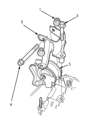
- 1. 10 x 1.25 mm, 44 Nm (4.5 kgf/m, 33 lbf/ft)
- 2. 12 x 1.25 mm, 44 Nm (4.5 kgf/m, 33 lbf/ft)
- 3. TRANSMISSION MOUNT
- 4. 12 x 1.25 (Long), 74 Nm (7.5 kgf/m, 54 lbf/ft)
- 5. TRANSMISSION MOUNT BRACKET
PDF p. 720 · 14-163
- 8.Install the right front mount/bracket.
- 9.Connect the ATF cooler hoses to the ATF cooler lines (See Page 14-173).
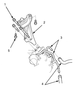
- 1. 10 x 1.25 mm, 54 Nm (5.5 kgf/m, 40 lbf/ft)
- 2. RIGHT FRONT MOUNT/BRACKET
- 3. ATF COOLER LINES
- 4. ATF COOLER HOSES
- 5. 10 x 1.25 mm, 44 Nm (4.5 kgf/m, 33 lbf/ft)
- 10.Install the transmission housing mounting bolts.
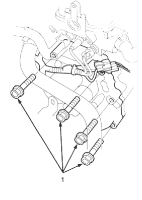
- 1. TRANSMISSION HOUSING MOUNTING BOLT 12 x 1.25 mm, 64 Nm (6.5 kgf/m, 47 lbf/ft)
- 11.Remove the transmission jack and the hoist, then remove the hoist bracket from the engine.
- 12.
Attach the flywheel to the drive plate with eight bolts and tighten them as follows:
Rotate the crankshaft pulley as necessary to tighten the bolts to half of the specified torque, then to the final torque, in a criss-cross pattern. After tightening the last bolt, check that the crankshaft rotate freely.
- 13.Install the flywheel cover then install the front stiffener.
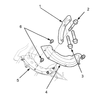
- 1. FRONT STIFFENER
- 2. 10 x 1.25 mm, 44 Nm (4.5 kgf/m, 33 lbf/ft)
- 3. 8 x 1.25 mm, 24 Nm (2.4 kgf/m, 17 lbf/ft)
- 4. FLYWHEEL COVER
- 5. DRIVE PLATE
- 6. 6 x 1.0 mm, 12 Nm (1.2 kgf/m, 8.7 lbf/ft)
- 14.Install the rear mount/bracket.
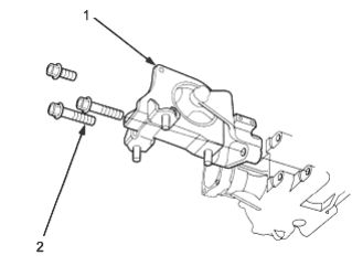
- 1. REAR MOUNT/BRACKET
- 2. 10 x 1.25 mm, 44 Nm (4.5 kgf/m, 33 lbf/ft)
PDF p. 721 · 14-164
- 15.Install new set rings on the ends of the intermediate shaft and the right driveshaft (see section 18).
- 16.
Install the intermediate shaft.
NOTE:
- While installing the intermediate shaft in the differential, be sure not to allow dust and other foreign particles to enter into the transmission.
- Clean the areas where the intermediate shaft contacts the transmission (differential) thoroughly with solvent or carburetor cleaner and dry with compressed air.
- 17.Install the rear stiffener.
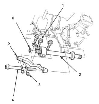
- 1. 10 x 1.25 mm, 39 Nm (4.0 kgf/m, 29 lbf/ft)
- 2. INTERMEDIATE SHAFT
- 3. 8 x 1.25 mm, 24 Nm (2.4 kgf/m, 17 lbf/ft)
- 4. 10 x 1.25 mm, 44 Nm (4.5 kgf/m, 33 lbf/ft)
- 5. REAR STIFFENER
- 6. SET RING Replace
- 18.
Install the right and left driveshafts (see section 18).
NOTE:
- While installing the right driveshaft in the differential, be sure not to allow dust and other foreign particles to enter into the transmission.
- Clean the areas where the right driveshaft contacts the transmission (differential) thoroughly with solvent or carburettor cleaner and dry with compressed air.
- Turn the right and left steering knuckle fully outward and slide the right driveshaft into the differential until you feel its spring clip engages the side gear. Slide the left driveshaft into the intermediate shaft until you feel the spring clip of the intermediate shaft engages the left driveshaft.
- 19.Install the propeller shaft to the transfer assembly by aligning the reference mark.
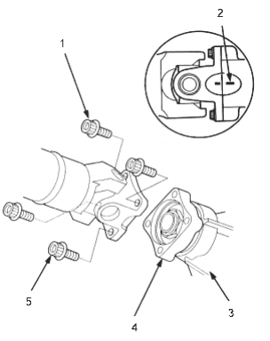
- 1. 8 x 1.25 mm, 32 Nm (3.3 kgf/m, 24 lbf/ft) Replace.
- 2. REFERENCE MARK
- 3. TRANSFER ASSEMBLY
- 4. TRANSFER FLANGE
- 5. PROPELLER SHAFT
- 20.Install the exhaust pipe A
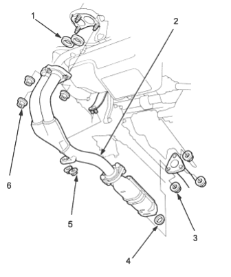
- 1. GASKET Replace.
- 2. EXHAUST PIPE A
- 3. 10 x 1.25 mm, 33 Nm (3.4 kgf/m, 25 lbf/ft) Replace
- 4. GASKET Replace
- 5. 8 x 1.25 m, 16 Nm (1.6 kgf/m, 12 lbf/ft) Replace.
- 6. 10 x 1.25 mm, 54 Nm (5.5 kgf/m, 40 lbf/ft) Replace.
PDF p. 723 · 14-165
- 21.Install the rear beam
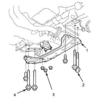
- 1. REAR BEAM
- 2. 12 x 1.25 mm, 64 Nm (6.5 kgf/m, 47 lbf/ft)
- 3. 10 x 1.25 mm, 38 Nm (3.9 kgf/m, 28 lbf/ft)
- 4. 12 x 1.25 mm, 64 Nm (6.5 kgf/m, 47 lbf/ft)
- 22.Install the ball joints on the lower arms to both knuckles, then install the ball joint nuts and secure them with cotter pins.
- 23.Install the front stabiliser links on the lower arms, then install the flange nuts.
- 24.Install a 5 mm Allen wrench into the tip of the ball joint pin of the front stabiliser link, then tighten the flange nuts.
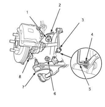
- 1. BALL JOINT NUT 12 x 1.25 mm, 49 - 59 Nm (5.0 - 6.0 kgf/m, 36 - 43 lbf/ft)
- 2. COTTER PIN, Replace
- 3. FRONT STABILISER LINK
- 4. BALL JOINT PIN
- 5. ALLEN WRENCH, 5 mm
- 6. FLANGE NUT Replace. 29 Nm (3.0 kgf/m, 22 lbf/ft)
- 7. LOWER ARM
- 25.Install the splash shield.
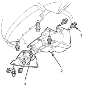
- 1. CLIP
- 2. SPLASH SHIELD
- 3. 6 x 10 mm, 12 Nm (1.2 kgf/m, 8.7 lbf/ft)
- 26.Install the shift cable bracket on the transmission.
- 27.Install the shift cable end on the control lever. Do not bend the shift cable excessively.
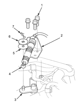
- 1. 8 x 1.25 mm, 26 Nm (2.7 kgf/m, 20 lbf/ft)
- 2. SHIFT CABLE BRACKET
- 3. CONTROL LEVER
- 4. SHIFT CABLE END
- 5. PLASTIC WASHER
- 6. WASHER
- 7. CLIP
- 8.KNUCKLE
PDF p. 724 · 14-166
- 28.Connect the secondary gear shaft speed sensor, driven pulley speed sensor, ECT sensor and VSS connectors, then install the harness clamp bracket.
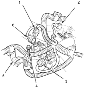
- 1. VSS CONNECTOR
- 2. ECT SENSOR CONNECTOR
- 3. DRIVE PULLEY SPEED SENSOR CONNECTOR
- 4. 6 x 1.0 mm, 12 Nm (1.2 kgf/m, 8.7 lbf/ft)
- 5. HARNESS CLAMP BRACKET
- 6. SECONDARY GEAR SHAFT SPEED SENSOR CONNECTOR
- 29.Connect the solenoid harness connector and the drive pulley speed sensor connector, then install the transmission ground cable terminals and the radiator hose clamp on the transmission hanger.
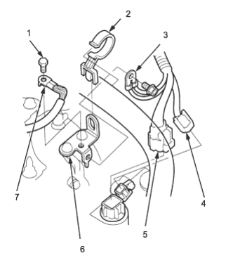
- 1. 6 x 1.0 mm, 12 Nm (1.2 kgf/m, 8.7 lbf/ft)
- 2. RADIATOR HOSE CLAMP
- 3. TRANSMISSION GROUND CABLE TERMINAL
- 4. DRIVE PULLEY SPEED SENSOR CONNECTOR
- 5. SOLENOID HARNESS CONNECTOR
- 6. TRANSMISSION HANGER
- 7. TRANSMISSION GROUND CABLE TERMINAL
- 30.Connect the starter cables on the starter with ring terminal crimped side facing out.
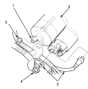
- 1. CLAMP BRACKET
- 2. STARTER
- 3. STARTER CABLES
- 4. 9 Nm (0.9 kgf/m, 7 lbf/ft)
- 5. HARNESS CLAMP
- 31.Install the distributor (see section 4).
- 32.Install the battery base and battery, then secure the battery with the battery hold-down bracket.
- 33.Refit the transmission with the recommended transmission fluid (See Page 14-84).
- 34.Connect the battery positive terminal and negative terminal to the battery.
- 35.Adjust the ignition timing (see section 4)
- 36.Start the engine. Set the parking brake and shift the transmission through all gears three times.
- 37.Check shift cable adjustment fluid (See Page 14-167).
- 38.Check that front wheel alignment (see section 18).
- 39.Let the engine reach normal operating temperature (the radiator fan comes on) with the transmission in P or N position, then turn it off and check the transmission fluid level fluid (See Page 14-83).
- 40.If the transmission assembly, start clutch assembly, lower valve body assembly, or engine assembly were replaced, or the engine assembly was overhauled, calibrate the feedback signal for the start clutch control in the PCM (See Page 14-71).
- 41.Perform road test (See Page 14-80) and (See Page 14-81).