PDF p. 707 · 14-150
NOTE:
- Coat all parts with transmission fluid.
- Replace the following parts:
- O-rings
- Sealing rings
- Sealing washers
- Gaskets
- Start clutch assembly and Secondary drive gear assembly
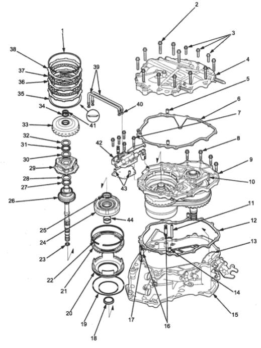
- 1. SNAP RING
- 2. 8 x 1.25 mm, 37 Nm (3.8 kgf/m, 27 lbf/ft) 11 bolts.
- 3. 6 x 1.0 mm, 12 Nm (1.2 kgf/m, 8.7 lbf/ft) 3 Bolts
- 4. RIGHT SIDE COVER
- 5. DOWEL PIN
- 6. RIGHT SIDE COVER GASKET
- 7. 6 x 1.0 mm, 12 Nm (1.2 kgf/m, 8.7 lbf/ft) 5 bolts
- 8. 8 x 1.25 mm, 29 Nm (3.0 kgf/m, 22 lbf/ft) 4 bolts
- 9. INTERMEDIATE HOUSING
ASSEMBLY - 10. ROLLER
- 11. ATF FEED PIPE
- 12. TRANSMISSION HOUSING GASKET
- 13. CONTROL SHAFT ASSEMBLY
- 14. DOWEL PIN
- 15. TRANSMISSION HOUSING
- 16. ATF FEED PIPES
- 17. O-RINGS
- 18. SNAP RING RETAINER
- 19. O-RINGS
- 20. REVERSE BRAKE PISTON
- 21. SPRING RETAINER/RETURN
SPRING ASSEMBLY - 22. SNAP RING
- 23. SEALING RING (RUBBER)
- 24. FORWARD CLUTCH ASSEMBLY
- 25. SNAP RING
- 26. SUN GEAR/INPUT SHAFT
ASSEMBLY - 27. THRUST NEEDLE BEARING
- 28. THRUST WASHER
- 29. CARRIER ASSEMBLY
- 30. THRUST WASHER
- 31. THRUST NEEDLE BEARING
- 32. THRUST WASHER
- 33. RING GEAR
- 34. THRUST SHIM, 25 x 31 mm, Selective part
- 35. DISC SPRING
- 36. PLATE
- 37. DISC
- 38. REVERSE BRAKE END PLATE
- 39. MANUAL VALVE BODY LINES
- 40. O-RINGS
- 41. SNAP RING
- 42. MANUAL VALVE BODY
- 43. DOWEL PIN
- 44. O-RINGS
PDF p. 708 · 14-151
- 1.Install the ATF feed pip in the transmission housing and install the three ATF feed pipes with new O-rings in the transmission housing.
- 2.Install the two dowel pins and new transmission housing gasket on the transmission housing.
- 3.Push the control shaft assembly toward the outside of the transmission housing, then install the intermediate housing assembly (four bolts).
- 4.Install the manual valve body separator plate and the two dowel pins on the intermediate housing, then install the manual valve body with the detent spring (five bolts).
- 5.Put the control shaft assembly back, then install the roller in the intermediate housing.
- 6.Install the reverse brake piston in the intermediate housing.
- 7.
Install the spring retainer/return spring assembly on the reverse brake piston.
NOTE: Install the return springs on the spring guides of the reverse brake piston securely.
- 8.Install the special tool to compress the return spring as shown.
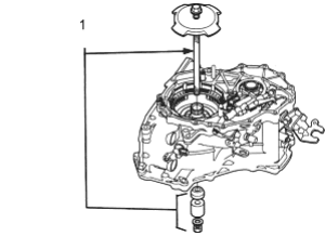
- 1. REVERSE BRAKE SPRING COMPRESSOR, 07TAE-P4V0110
NOTE: If the spring retainer tab is on the reverse brake piston, the spring retainer may be damaged. Be sure the spring retainer tab is not on the piston.
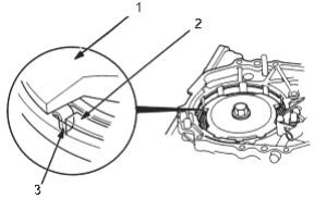
- 1. SPECIAL TOOL
- 2. REVERSE BRAKE PISTON
- 3. SPRING RETAINER TAB
- 9.Compress the return springs, then install the snap ring in the intermediate housing above the spring retainer.
- 10.Verify that the snap ring end gap is correct.
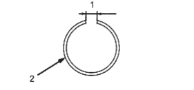
- 1. Minimum 15 mm, (0.59 in)
- 2. SNAP RING
- 11.Soak the reverse brake discs thoroughly in recommended transmission fluid (See Page 14-84) for minimum 30 minutes.
- 12.Install the disc spring on the reverse brake piston.
- 13.Starting with a reverse brake plate, alternately install the reverse brake plates and discs. Install the reverse brake end plate and the snap ring.
- 14.
Measure the clearance between the reverse brake end plate and the top disc with a dial indicator. Zero the dial indicator with a reverse brake end plate lowered and lift it up to the snap ring. The distance that the reverse brake and plate moves is the clearance between the reverse end plate and the top disc.
NOTE: Take measurements in at least three places and use the average as the actual clearance.
STANDARD: 0.45 - 0.75 mm (0.018 - 0.030 in)
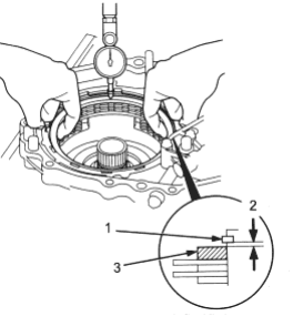
- 1. SNAP RING
- 2. Clearance
- 3. REVERSE BRAKE END PLATE
PDF p. 709 · 14-152
- 15.If the clearance is not within the standard, remove the reverse brake end plate and measure its thickness.
- 16.
Select and install a new reverse brake end plate, then recheck.
NOTE: If the thickest reverse brake end plate installed, but the clearance is still over the standard, replace the reverse brake discs and plates.
REVERSE BRAKE END PLATE
| Plate No. | Part Number | Thickness | |
| 1 | 22551-P4V-003 | 3.6 mm (0.142 in) | |
| 2 | 22552-P4V-003 | 3.8 mm (0.150 in) | |
| 3 | 22553-P4V-003 | 4.0 mm (0.157 in) | |
| 4 | 22554-P4V-003 | 4.2 mm (0.165 in) | |
| 5 | 22555-P4V-003 | 4.4 mm (0.173 in) | |
| 6 | 22556-P4V-003 | 4.6 mm (0.181 in) | |
| 7 | 22557-P4V-003 | 4.8 mm (0.189 in) | |
| 8 | 22558-P4V-003 | 5.0 mm (0.197 in) | |
- 17.After replacing the reverse brake end plate, make sure that the clearance is within the standard.
- 18.Remove the snap ring, reverse brake end plate, discs, plates and disc spring.
- 19.Install the snap ring retainer on the drive pulley shaft.
- 20.Wrap the drive pulley shaft splines with tape to prevent damage to the O-rings, then install new O-rings.
- 21.Install the forward clutch assembly on the drive pulley shaft, then install the snap ring.
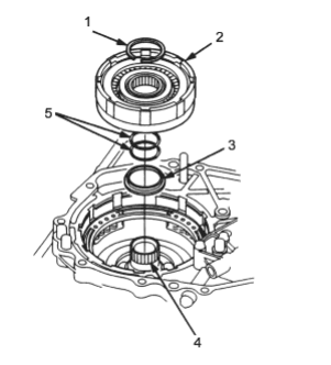
- 1. SNAP RING
- 2. FORWARD CLUTCH ASSEMBLY
- 3. SNAP RING RETAINER
- 4. DRIVE PULLEY SHAFT
- 5. O-RINGS
- 22.Verify that the outside diameter of the snap ring is correct.
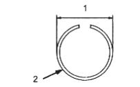
- 1. Maximum 41.4 mm, (1.63 in)
- 2. SNAP RING
- 23.Install the sun gear/input shaft assembly.
- 24.Install the thrust needle bearing and the thrust washer on the sun gear.
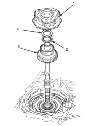
- 1. CARRIER ASSEMBLY
- 2. THRUST NEEDLE BEARING
- 3. SUN GEAR/INPUT SHAFT ASSEMBLY
- 4. THRUST WASHER
- 25.Install the carrier assembly on the forward clutch.
PDF p. 710 · 14-153
- 26.Install the thrust washer, the thrust needle bearing. and the thrust washer on the carrier assembly.
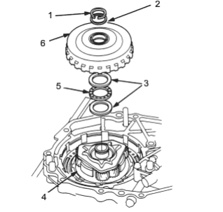
- 1. SNAP RING
- 2. THRUST SHIM, 25 x 31 mm, Selective part
- 3. THRUST WASHERS
- 4. CARRIER ASSEMBLY
- 5. THRUST NEEDLE BEARING
- 6. RING GEAR
- 27.Install the ring gear and the 25 x 31 mm thrust shim, then install the snap ring.
- 28.Verify that the outside diameter of the snap ring is correct.
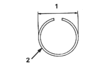
- 1. Maximum 30.7 mm, (1.21 in)
- 2. SNAP RING
- 29.
Measure the clearance between the 25 x 31 mm thrust shim and the snap ring.
STANDARD: 0.05 - 0.11 mm (0.0020 - 0.0043 in)
NOTE: Take measurements in at least three places and use the average as the actual clearance.
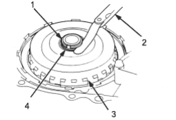
- 1. SNAP RING
- 2. FEELER GAUGE
- 3. RING GEAR
- 4. THRUST SHIM, 25 x 31 mm
- 30.If the clearance is out of tolerance, remove the 25 x 31 mm thrust shim and measure its thickness.
- 31.Select and install a new 25 x 31 mm thrust shim, then recheck.
THRUST SHIM, 25 X 31 MM
| No. | Part Number | Thickness |
| A | 90451-P4V-000 | 1.05 mm (0.041 in) |
| B | 90452-P4V-000 | 1.12 mm (0.044 in) |
| C | 90453-P4V-000 | 1.19 mm (0.047 in) |
| D | 90454-P4V-000 | 1.26 mm (0.050 in) |
| E | 90455-P4V-000 | 1.33 mm (0.052 in) |
| F | 90456-P4V-000 | 1.40 mm (0.055 in) |
| G | 90457-P4V-000 | 1.47 mm (0.058 in) |
| H | 90458-P4V-000 | 1.54 mm (0.061 in) |
| I | 90459-P4V-000 | 1.61 mm (0.063 in) |
| J | 90460-P4V-000 | 1.68 mm (0.066 in) |
| K | 90461-P4V-000 | 1.75 mm (0.069 in) |
| L | 90462-P4V-000 | 1.82 mm (0.072 in) |
| M | 23980-P4V-000 | 1.085 mm (0.0427 in) |
| N | 23981-P4V-000 | 1.055 mm (0.0454 in) |
| O | 23982-P4V-000 | 1.225 mm (0.0482 in) |
| P | 23983-P4V-000 | 1.295 mm (0.0510 in) |
| Q | 23984-P4V-000 | 1.265 mm (0.0537 in) |
| R | 23985-P4V-000 | 1.435 mm (0.0565 in) |
| S | 23986-P4V-000 | 1.505 mm (0.0593 in) |
| T | 23987-P4V-000 | 1.575 mm (0.0620 in) |
| U | 23988-P4V-000 | 1.645 mm (0.0648 in) |
| V | 23989-P4V-000 | 1.715 mm (0.0675 in) |
| W | 23990-P4V-000 | 1.785 mm (0.0703 in) |
PDF p. 711 · 14-154
- 32.After replacing the 25 x 31 mm thrust shim, make sure that the clearance is within the tolerance and the snap ring outside diameter is correct as described in the step 28.
- 33.Install the disc spring in the direction shown.
- 34.Starting with a reverse brake plate, alternately install the reverse brake plates and discs. Install selected reverse brake end plate, then install the snap ring.
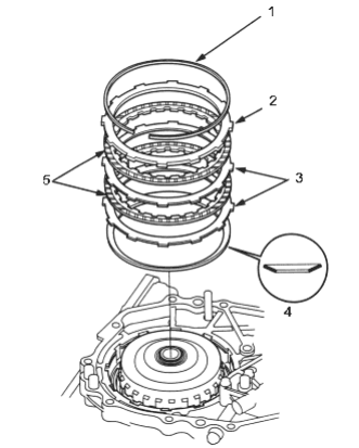
- 1. SNAP RING
- 2. REVERSE BRAKE END PLATE
- 3. REVERSE BRAKE PLATE
- 4. DISC SPRING, Install in this direction
- 5. REVERSE BRAKE DISC
- 35.Verify that the snap ring end gap is correct.
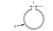
- 1. Minimum 18 mm, (0.71 in)
- 2. SNAP RING
- 36.Install the manual valve body lines A and B with new O-rings on the manual valve body and the intermediate housing.
- 37.Install the two dowel pins and new right side cover gasket on the intermediate housing, then install the new O-rings over the ATF feed pipes.
- 38.Install the right side cover on the intermediate housing.
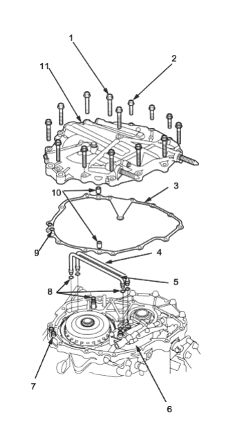
- 1. 8 x 1.25 mm, 37 Nm (3.8 kgf/m, 27 lbf/ft) 11 Bolts
- 2. 6 x 1.0 mm, 12 Nm (1.2 kgf/m, 8.7 lbf/ft) 3 Bolts
- 3. RIGHT SIDE COVER GASKET, Replace
- 4. MANUAL VALVE BODY LINE A
- 5. MANUAL VALVE BODY LINE B
- 6. MANUAL VALVE BODY
- 7. ATF FEED PIPE
- 8. O-RINGS, Replace
- 9. O-RINGS, Replace
- 10. DOWEL PINS
- 11. RIGHT SIDE COVER
PDF p. 712 · 14-155
- 39.Install the parking brake pawl, pawl spring and pawl shaft on the transmission housing, then move the control lever to any position other than P.
- 40.Install the secondary gear shaft with the selected 25 x 35 mm thrust shim (See Page 14-122).
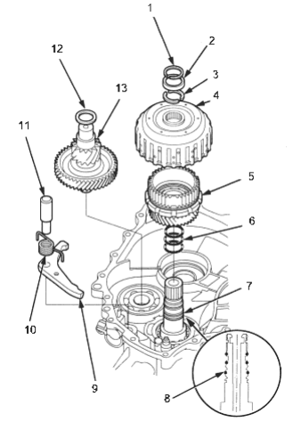
- 1. SNAP RING
- 2. COTTER RETAINER
- 3. COTTERS, 25.5 mm, Selective part
- 4. START CLUTCH ASSEMBLY
- 5. SECONDARY DRIVE GEAR ASSEMBLY
- 6. O-RING, Replace
- 7. DRIVEN PULLEY SHAFT
- 8. O-RING, Replace
- 9. PARKING BRAKE PAWL
- 10. PARKING BRAKE PAWL SPRING
- 11. PARKING BRAKE PAWL SHAFT
- 12. THRUST SHIM, 25 X 35 mm
- 13. SECONDARY GEAR SHAFT
- 41.Wrap the driven pulley shaft splines with tape to prevent damage to the O-rings, then install the new O-rings.
- 42.Assemble the secondary drive gear assembly in the start clutch assembly, then install them on the driven pulley shaft.
- 43.Pull the handle of the special tool up, then install the tip of it into the driven pulley shaft hole and set the special tool on the start clutch.
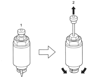
- 1. START CLUTCH INSTALLER, 07TAE-P4V0130
- 2. Pull handle.
PDF p. 713 · 14-156
- 44.Push the handle of the special tool, then tighten the nut to seat the secondary drive gear assembly on the drive pulley shaft securely.
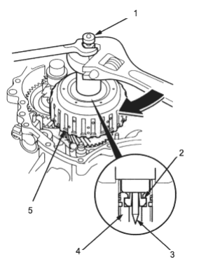
- 1. START CLUTCH INSTALLER, 07TAE-P4V0130
- 2. TIP
- 3. END OF HANDLE
- 4. DRIVEN PULLEY SHAFT
- 5. START CLUTCH ASSEMBLY
- 45.Pull the handle of the special tool up and remove the special tool.
- 46.
Install the cotters, then measure the clearance between the cotters and the start clutch guide.
STANDARD: 0 - 0.13 mm (0 - 0.005 in)
NOTE: Take measurements in at least three places and use the average as the actual clearance.
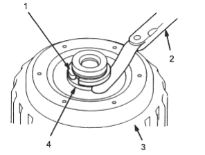
- 1. COTTERS, 25.5 mm
- 2. FEELER GAUGE
- 3. START CLUTCH
- 4. START CLUTCH GUIDE
- 47.If the clearance is not within the standard, remove the cotters and measure their thickness.
- 48.Select and install new cotters, then recheck. COTTERS, 25.5 mm
| No. | Part Number | Thickness | |
| A | 90429-P4V-000 | 2.9 mm (0.114 in) | |
| B | 90430-P4V-000 | 3.0 mm (0.118 in) | |
| C | 90431-P4V-000 | 3.1 mm (0.122 in) | |
| D | 90432-P4V-000 | 3.2 mm (0.126 in) | |
- 49.After replacing the 25.5 mm cotters, make sure that the clearance is the standard.
- 50.Install the cotter retainer and the snap ring.
- 51.Verify that the outside diameter of the snap ring is correct.
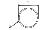
- 1. Minimum 33.9 mm, (1.33 in)
- 2. SNAP RING
- 52.Install the thrust washers, the ATF pump drive sprocket hub and the 22 x 28 mm thrust shim on the input shaft, then install the snap ring.
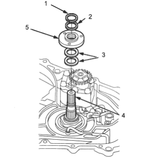
- 1. SNAP RING
- 2. THRUST SHIM, 22 x 28 mm, Selective part
- 3. THRUST WASHERS
- 4. INPUT SHAFT
- 5. ATF PUMP DRIVE SPROCKET HUB
PDF p. 714 · 14-157
- 53.Verify that the outside diameter of the snap ring is correct.
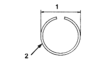
- 1. Maximum 26.3 mm, (1.04 in)
- 2. SNAP RING
- 54.
Measure the clearance between the 22 x 28 mm thrust shim and the snap ring.
STANDARD: 0.37 - 0.65 mm (0.015 - 0.026 in)
NOTE: Take measurements in at least three places and use the average as the actual clearance.
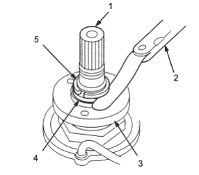
- 1. INPUT SHAFT
- 2. FEELER GAUGE
- 3. ATF PUMP DRIVE SPROCKET HUB
- 4. THRUST SHIM, 22 x 28 mm
- 5. SNAP RING
- 55.If the clearance is out of tolerance, remove the 22 x 28 mm thrust shim and measure its thickness.
- 56.Select and install a new 22 x 28 mm thrust shim, then recheck.
THRUST SHIM, 22 x 28 mm
| No. | Part Number | Thickness | |
| C | 90573-P4V-000 | 1.15 mm (0.045 in ) | |
| D | 90574 P4V-000 | 1.40 mm (0.055 in ) | |
| E | 90575-P4V-000 | 1.65 mm (0.065 in ) | |
| F | 90576-P4V-000 | 1.90 mm (0.075 in ) | |
| G | 90577-P4V-000 | 2.15 MM (0.085 in ) | |
| H | 90578-P4V-000 | 2.40 mm (0.095 in ) | |
- 57.After replacing the 22 x 28 mm thrust shim, make sure that the clearance is within tolerance and the snap ring outside diameter is correct.
- 58.Install the pitot flange using its cutout as shown to clear the pitot pipes.
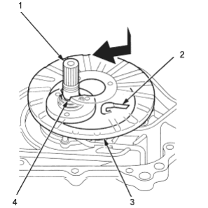
- 1. INPUT SHAFT
- 2. PITOT PIPE
- 3. PITOT FLANGE
- 4. CUT OUT
- 59.Install the ATF pump drive sprocket and put the ATF pump drive chain on the ATF pump drive and driven sprockets, then install and tighten the bolts (three bolts).
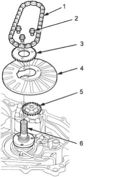
- 1. ATF PUMP DRIVE CHAIN
- 2. 6 x 1.0 mm, 12 Nm (1.2 kgf/m, 8.7 lbf/ft)
- 3. ATF PUMP DRIVE SPROCKET
- 4. PITOT FLANGE
- 5. ATF PUMP
- 6. INPUT SHAFT
PDF p. 715 · 14-158
- 60.Install the differential assembly.
- 61.Install the ATF passage pipe assembly with new O-rings.
- 62.Install the three dowel pins and new flywheel gasket on the transmission housing.
- 63.Install the flywheel housing on the transmission housing.
- 64.Install the flywheel housing mounting bolts and tighten them:
- 18 bolts and connector bracket from the flywheel housing side
- 3 bolts from the transmission housing side.
- 65.Install the ATF passage pipe holder assembly.
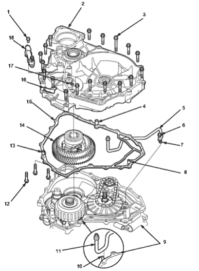
- 1. 6 x 1.0 mm, 12 Nm (1.2 kgf/m, 8.7 lbf/ft).
- 2. FLYWHEEL HOUSING.
- 3. FLYWHEEL HOUSING MOUNTING BOLT 8 x 1.25 mm, 29 Nm
(3.0 kgf/m, 22 lbf/ft) 18 Bolts - 4. DOWEL PIN 12 x 20 mm
- 5. ATF PASSAGE PIPE ASSEMBLY
- 6. 6 x 1.0 mm, 12 Nm (1.2 kgf/m. 8.7 lbf/ft).
- 7. O-RING Replace.
- 8. DOWEL PIN 10 x 16 mm.
- 9. TRANSMISSION HOUSING
- 10. PASSAGE PIPE GUIDE
- 11. ATF PASSAGE PIPE ASSEMBLY
- 12. FLYWHEEL HOUSING MOUNTING BOLT 8 x 1.25 mm, 29 Nm (3.0 kgf/m, 22 lbf/ft) 3 Bolts
- 13. DOWEL PIN 10 x 16 mm
- 14. DIFFERENTIAL ASSEMBLY
- 15. FLYWHEEL HOUSING GASKET Replace.
- 16. CONNECTOR BRACKET
- 17. O-RING Replace.
- 18. ATF PASSAGE PIPE HOLDER ASSEMBLY
PDF p. 716 · 14-159
- 66.Install the solenoid harness connector with new O-ring and install the lower valve body assembly with three dowel pins and eight bolts.
- 67.Install the ATF strainer with new O-ring and two bolts.
- 68.If necessary, assemble the ATF pan, ATF filter and the ATF cooler inlet line ( See Page 14-88).
- 69.Install the ATF pan with two dowel pins, new gasket and 14 bolts.
- 70.Secure the ATF cooler inlet line with 8 mm bolt at the bracket.
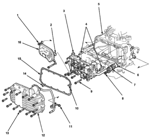
- 1. 6 x 1.0 mm, 12 Nm (1.2 kgf/m, 8.7 lbf/ft) 2 bolts
- 2. O-RING Replace..
- 3. LOWER VALVE BODY ASSEMBLY
- 4. DOWEL PINS
- 5. TRANSMISSION HOUSING
- 6. O-RING Replace
- 7. SOLENOID HARNESS CONNECTOR
- 8. 6 x 1.0 mm, 12 Nm (1.2 kgf/m, 8.7 lbf/ft)
- 9. 6 x 1.0 mm, 12 Nm (1.2 kgf/m, 8.7 lbf/ft) 8 Bolts.
- 10. DOWEL PIN
- 11. ATF COOLER INLET LINE BRACKET BOLT 8 x 1.25 mm, 26 Nm (2.7 kgf/m, 20 lbf/ft)
- 12. ATF PAN.
- 13. 6 x 1.0 mm, 12 Nm 1.2 kgf/m, 8.7 lbf/ft) 14 Bolts
- 14. DOWEL PIN
- 15. ATF PAN GASKET Replace.
- 16. ATF STRAINER
PDF p. 717 · 14-160
- 71.Install the breather cap on the breather pipe so its arrow points to the flywheel housing
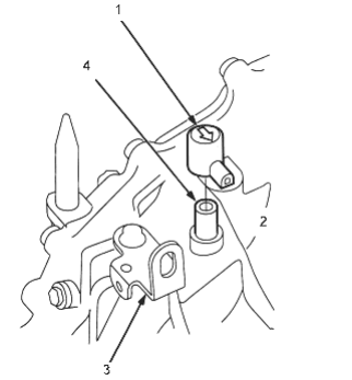
- 1. BREATHER CAP
- 2. FLYWHEEL HOUSING SIDE
- 3. TRANSMISSION HANGER
- 4. BREATHER PIPE
NOTE: Steps 72 and 73 are applied to 4WD transmission.
- 72.Clean the areas where the transfer assembly contacts the transmission with solvent or carburetor cleaner and dry them with compressed air, then apply to contact areas with transmission fluid.
- 73.Install the transfer assembly with new O-rings. Do not allow dust and other foreign particles to enter into the transmission.
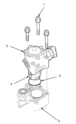
- 1. 10 x 1.25 m, 44 Nm (4.5 kgf/m, 33 lbf/ft)
- 2. O-RING Replace
- 3. FLYWHEEL HOUSING
- 4. DOWEL PIN
- 5. TRANSFER ASSEMBLY