PDF p. 664 · 14-110
NOTE:
- The illustration shows the 4WD transmission; the 2WD transmission does not have the transfer assembly and related parts to the transfer.
- Clean all parts thoroughly in solvent or carburettor cleaner and dry them with compressed air.
- Blow out all passages.
- When remove the transmission housing/flywheel housing, replace the following:
- O-rings
- Start clutch assembly
- Secondary drive gear assembly
- Flywheel housing gasket
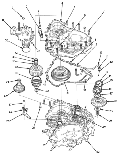
- 1. 10 x 1.25 mm, 3 Bolts.
- 2. ATF PASSAGE PIPE HOLDER ASSEMBLY
- 3. 6 x 1.0 mm, 2 Bolts
- 4. FLYWHEEL HOUSING
- 5. CONNECTOR BRACKET
- 6. O-RING Replace.
- 7. FLYWHEEL HOUSING MOUNTING BOLTS 18 Bolts
- 8. DOWEL PIN
- 9. FLYWHEEL HOUSING GASKET Replace.
- 10. ATF PASSAGE PIPE ASSEMBLY
- 11. 6 x 1.0 mm, 1 Bolt.
- 12. O-RING Replace.
- 13. ATF PUMP DRIVE CHAIN
- 14. SNAP RING.
- 15. THRUST SHIM, 22 x 28 mm Selective part
- 16. 6 x 1.0 mm, , 3 Bolts
- 17. ATF PUMP DRIVE SPROCKET
- 18. PITOT FLANGE
- 19. ATF PUMP DRIVE SPROCKET HUB
- 20. THRUST WASHER
- 21. INPUT SHAFT
- 22. TRANSMISSION HOUSING
- 23. DRIVEN PULLEY SHAFT
- 24. FLYWHEEL HOUSING MOUNTING BOLT, 3 Bolts
- 25. PARKING BRAKE PAWL
- 26. PARKING BRAKE PAWL SPRING
- 27. PARKING BRAKE PAWL SHAFT
- 28. SECONDARY GEAR SHAFT
- 29. THRUST SHIM, 25 x 35 mm Selective part.
- 30. SECONDARY DRIVE GEAR ASSEMBLY
- 31. START CLUTCH ASSEMBLY
- 32. COTTERS, 25.5 mm
Selective part. - 33. COTTER RETAINER
- 34. SNAP RING
- 35. O-RING Replace.
- 36. TRANSFER ASSEMBLY (4WD)
- 37. DOWEL PIN
- 38. DOWEL PIN
- 39. DIFFERENTIAL ASSEMBLY
- 40. O-RING Replace.
- 41. DOWEL PIN
PDF p. 665 · 14-111
- 1.Remove the transfer assembly from the transmission for 4WD transmission.
- 2.Remove the ATF passage pipe holder assembly.
- 3.Remove the flywheel housing mounting bolts:
- 18 bolts from the flywheel housing side.
- 3 bolts from the transmission housing side.
- 4.Remove the flywheel housing.
- 5.Remove the ATF pump drive sprocket (three bolts), then remove the ATF pump drive chain.
- 7.Move the pitot flange toward its cutout, then remove the pitot flange.
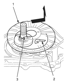
- 1. PITOT FLANGE
- 2. PITOT PIPE
- 3. CUTOUT
- 8.Remove the snap ring securing the ATF pump drive sprocket hub, then remove the 22 x 28 mm thrust shim, the ATF pump drive sprocket hub and the thrust washers.
- 9.Remove the differential assembly.
- 10.Remove the parking brake pawl shaft, the parking brake pawl spring and the parking brake pawl.
- 11.Remove the snap ring securing the start clutch, then remove the cotter retainer and the cotters.
- 12.Set the special tool on the start clutch and attach the pawl of the special tool to the parking gear securely as shown.
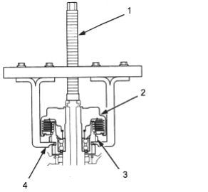
- 1. START CLUTCH REMOVER 07TAE-P4V0120
- 2. START CLUTCH ASSEMBLY Replace.
- 3. PARK GEAR
- 4. PAWL
- 13.Remove the start clutch and the secondary drive gear assembly using the special tool, then remove the secondary gear shaft.
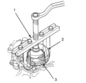
- 1. START CLUTCH REMOVER 07TAE-P4V0120
- 2. START CLUTCH ASSEMBLY
- 3. PARK GEAR