PDF p. 666 · 14-112
NOTE:
- Clean all parts in solvent or carburettor cleaner and dry them with compressed air.
- Blow out all passages.
- When removing the right side cover/intermediate housing, replace the following parts.
- O-rings
- Right side cover gasket
- Transmission housing gasket
- Sealing washers
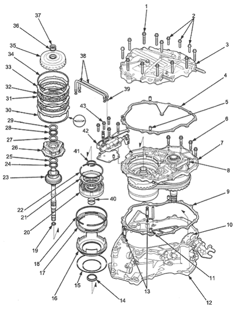
- 1. 8 x 1.25 mm, 11 Bolts.
- 2. 6 x 1.0 mm, 3 Bolts
- 3. RIGHT SIDE COVER
- 4. RIGHT SIDE COVER GASKET Replace
- 5. DOWEL PIN
- 6. 8 x 1.25 mm, 4 Bolts.
- 7. INTERMEDIATE HOUSING
ASSEMBLY - 8. ROLLER
- 9. TRANSMISSION HOUSING GASKET Replace
- 10. CONTROL SHAFT ASSEMBLY
- 11. DOWEL PIN
- 12. TRANSMISSION HOUSING
- 13. O-RINGS Replace
- 14. SNAP RING RETAINER
- 15. O-RINGS Replace
- 16. REVERSE BRAKE PISTON
- 17. SPRING RETAINER/RETURN SPRINGS ASSEMBLY
- 18. SNAP RING
- 19. SEALING RING (RUBBER) Replace
- 20. FORWARD CLUTCH ASSEMBLY
- 21. CLUTCH END PLATE
- 22. SNAP RING
- 23. SUN GEAR/INPUT SHAFT
ASSEMBLY - 24. THRUST NEEDLE BEARING
- 25. THRUST WASHER
- 26. CARRIER ASSEMBLY
- 27. THRUST WASHER
- 28. THRUST NEEDLE BEARING
- 29. THRUST WASHER
- 30. DISC SPRING
- 31. PLATE
- 32. DISC
- 33. REVERSE BRAKE END PLATE.
- 34. SNAP RING
- 35. RING GEAR
- 36. THRUST SHIM 25 x 31 mm Selective part.
- 37. SNAP RING
- 38. MANUAL VALVE BODY LINES
- 39. 0-RINGS Replace
- 40. O-RING Replace
- 41. SNAP RING
- 42. MANUAL VALVE BODY
- 43. 6 x 1.0 mm, BOLT
PDF p. 667 · 14-113
- 1.Remove the right side cover (three 6 mm bolts, eleven 8 mm bolts).
- 2.Remove the manual valve body lines A and B.
- 3.Remove the snap ring securing the ring gear, then remove the thrust shim and the ring gear.
- 4.Remove the snap ring securing the reverse brake discs and plates, then remove the reverse brake end plate, brake discs, brake plates and disc spring.
- 5.Remove the carrier assembly with the thrust washers and the thrust needle bearing, from the forward clutch.
- 6.Remove the sun gear/input shaft assembly by pulling it.
- 7.Remove the snap ring securing the forward clutch and remove the snap ring securing the forward clutch end plate, then remove the forward clutch end plate.
- 8.Reinstall the carrier on the forward clutch, then secure the carrier assembly with the snap ring on the forward clutch end plate.
- 9.Remove the forward clutch and carrier assembly together.
- 10.Install the special tool to remove the snap ring securing the reverse brake return spring retainer as shown.
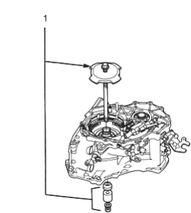
- 1. REVERSE BRAKE SPRING COMPRESSOR, 07TAE-P4V0110
- 11.
Compress the return springs, then remove the snap ring.
NOTE: If the spring retainer tab is on the reverse brake piston, the spring retainer may be damaged. Be sure the spring retainer tab is not on the piston.
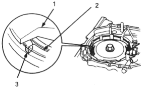
- 1. SPECIAL TOOL
- 2. PISTON
- 3. SPRING RETAINER TAB
- 12.Remove the special tool, then remove the spring retainer/return spring assembly.
- 13.Remove the sealing bolt securing the reverse brake pressure inspection hole.
- 14.Apply air pressure to the inspection hole to remove the reverse brake piston.
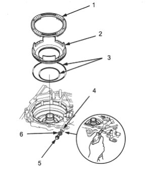
- 1. SPRING RETAINER/RETURN SPRING ASSEMBLY
- 2. REVERSE BRAKE PISTON
- 3. O-RINGS Replace.
- 4. REVERSE BRAKE PRESSURE INSPECTION HOLE
- 5. 8 x 1.25 mm, 18 Nm (1.8 kgf/m, 13 lbf/ft)
- 6. SEALING WASHER Replace.
- 15.Remove the snap ring retainer from the drive pulley shaft.
- 16.Remove the manual valve body (five bolts).
- 17.Remove the roller and push the control shaft assembly toward the outside of the transmission housing, then remove the intermediate housing (four bolts).