PDF p. 545 · 13-71
- 1.Install the differential assembly in the clutch housing.
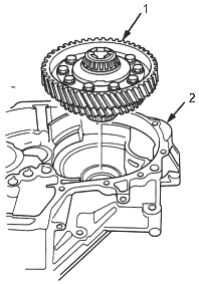
- 1. DIFFERENTIAL ASSEMBLY
- 2. CLUTCH HOUSING
- 2.Install the spring washer as washer with the angle against the clutch housing as shown.
- 3.
Insert the mainshaft and countershaft into the shift forks and install them as an assembly.
NOTE: Before installing the mainshaft and countershaft assemblies, tape the mainshaft splines to protect them.
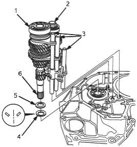
- 1. MAINSHAFT ASSEMBLY
- 2. COUNTERSHAFT ASSEMBLY
- 3. SHIFT FORKS
- 4. SPRING WASHER
- 5. WASHER
- 6. Tape the mainshaft splines
- 4.Install the reverse idle gear and reverse gear shaft in the clutch housing.
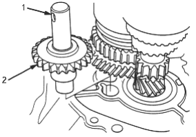
- 1. REVERSE GEAR SHAFT
- 2. REVERSE IDLE GEAR
- 5.Install the reverse shift holder in the clutch housing with the 5th/reverse shift piece pin positioned in the slot of the reverse shift fork.
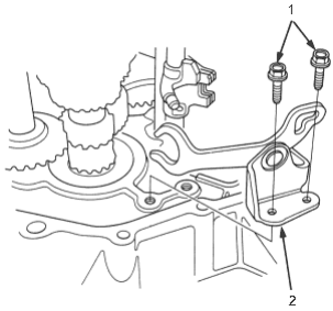
- 1. 6 x 1.0 mm, 15 Nm (1.5 kgf/m, 11 lbf/ft)
- 2. REVERSE SHIFT HOLDER
PDF p. 546 · 13-72
- 6.Install the reverse lock cam on the clutch housing.
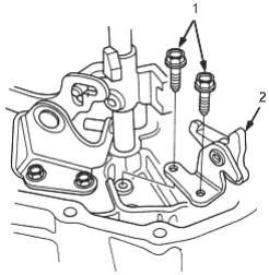
- 1. 6 x 1.0 mm, 15 Nm (1.5 kgf/m, 11 lbf/ft)
- 2. REVERSE LOCK CAM
- 7.Install the oil seal.
- 8.Install the select lever, spring washer and springs on the select arm.
- 9.Install the select arm and spring pin.
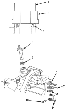
- 1. HANDLE DRIVER, 07749-001000
- 2. DRIVER ATTACHMENT, 32 x 35 mm, 07746-0010100
- 3. OIL SEAL, Replace
- 4. SELECT LEVER
- 5. OIL SEAL, Replace
- 6. SELECT RETURN SPRING
- 7. 5TH/REVERSE SELECT RETURN SPRING
- 8. THRUST WASHER
- 9. SELECT ARM
- 10. SPRING PIN, Replace
- 10.Install the select spring bolt.
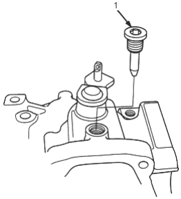
- 1. SELECT SPRING BOLT, 39 Nm (4.0 kgf/m, 29 lbf/ft)
- 11.
Install the oil guide M plate, 78 mm shim and oil gutter plate in the transmission housing.
NOTE: Select the 78 mm shim according to the measurements made on page 13-64.
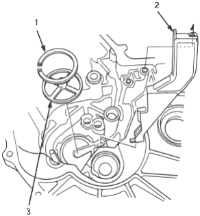
- 1. 78 mm SHIM
- 2. OIL GUTTER PLATE
- 3. OIL GUIDE M PLATE
PDF p. 547 · 13-73
- 12.
Apply liquid gasket to the surface of the transmission housing as shown.
NOTE:
- Use liquid gasket (P/N 08C70-K00234M).
- Remove the dirty fluid from the sealing surface.
- Seal the entire circumference of the bolt holes to prevent fluid leakage.
- If 20 minutes have passed after applying liquid gasket, reapply it and assemble the housings.
- Allow it to cure at least 20 minutes after assembly before filling the transmission with oil.
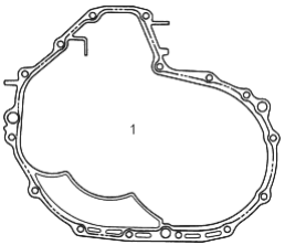
- 1. ---- Liquid Gasket
- 13.Install the 14 x 20 mm dowel pins.
- 14.
Set the stopper ring as shown. Place the transmission housing over the clutch housing, being careful to line up the shafts.
NOTE: Align the stopper ring with the 5th shift fork.
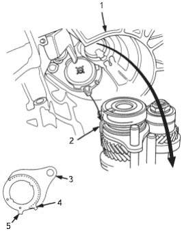
- 1. TRANSMISSION HOUSING
- 2. STOPPER RING
- 3. 5TH SHIFT FORK
- 4. Align point.
- 5. STOPPER RING
- 15.Lower the transmission housing with the snap ring pliers, and set the snap ring into the groove of the countershaft bearing.
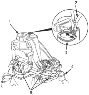
- 1. TRANSMISSION HOUSING
- 2. SNAP RING PLIERS, 07LGC-0010100
- 3. SNAP RING
- 4. CLUTCH HOUSING
- 5. DOWEL PINS
- 16.Check that the snap ring is securely seated in the groove of the countershaft bearing.
Dimension A as installed: 3.6 - 6.3 mm
(0.142 - 0.248 in)
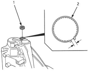
- 1. 32 mm SEALING BOLT, 25 Nm (2.5 kgf/m, 18 lbf/ft)
- 2. SNAP RING
PDF p. 548 · 13-74
- 17.
Install the 32 mm sealing bolt.
NOTE: Apply liquid gasket (P/N 0Y740-99986 or 08C70-X0134S) to the threads.
- 18.Install transmission hanger, then tighten the bolts in a crisscross pattern in several steps as shown.
8 x 1.25 mm bolts: 27 Nm (2.8 kgf/m, 20 lbf/ft)
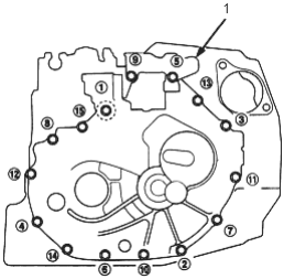
- 1. TRANSMISSION HANGER
- 19.Install flange bolt, washers, drain plug and filler plug.
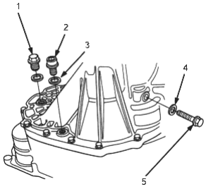
- 1. FILLER PLUG, 44 Nm (4.5 kgf/m, 33 lbf/ft)
- 2. DRAIN PLUG, 39 Nm (4.0 kgf/m, 29 lbf/ft)
- 3. WASHER, Replace
- 4. WASHER, Replace
- 5. FLANGE BOLT, 44 Nm (4.5 kgf/m, 33 lbf/ft)
- 20.Install the steel balls, springs, washers, set ball screws and back-up light switch.
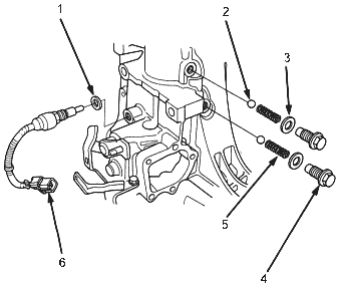
- 1. WASHER, Replace
- 2. STEEL BALL 5/16 in D.
- 3. WASHER, Replace
- 4. SET BALL SCREW, 22 Nm (2.2 kgf/m, 16 lbf/ft)
- 5. SPRING L. 26.1 mm (1.03 in)
- 6. BACK-UP LIGHT SWITCH, 22 Nm (2.2 kgf/m, 16 lbf/ft)
- 21.Install the vehicle speed sensor (VSS).
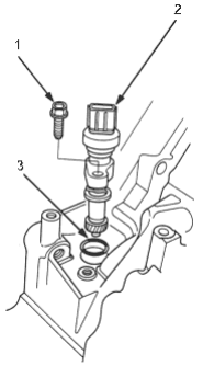
- 1. 8 x 1.25 mm, 22Nm (2.2 kgf/m, 16 lbf/ft)
- 2. VEHICLE SPEED SENSOR
- 3. O-RING, Replace