PDF p. 542 · 13-68
- 1.Remove the 78 mm shim and oil guide plate from the transmission housing.
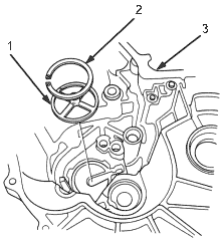
- 1. OIL GUIDE PLATE
- 2. 78 mm SHIM
- 3. TRANSMISSION HOUSING
- 2.Install the 3rd/4th synchro hub, spacer collar, 5th synchro hub, spacer and ball bearing on the mainshaft, then install the above assembly in the transmission housing.
- 3.Install the washer on the mainshaft.
- 4.
Measure distance (A) between the end of the transmission housing and washer.
NOTE:
- Use a straight edge and vernier caliper.
- Measure at three locations and average the reading.
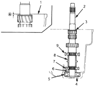
- 1. END of TRANSMISSION HOUSING
- 2. MAINSHAFT
- 3. WASHER
- 4. TRANSMISSION HOUSING
- 5. BALL BEARING
- 6. SPACER
- 7. 5TH SYNCHRO HUB
- 8. SPACER COLLAR
- 9. 3RD/4TH SYNCHRO HUB
- 5.
Measure distance (B) between the end of the clutch housing and bearing inner race.
NOTE:
- Use a straight edge and vernier caliper.
- Measure at three locations and average the reading.
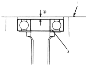
- 1. END of CLUTCH HOUSING
- 2. INNER RACE of BALL BEARING
- 6.
Select the proper 78 mm shim from the chart by using the formula below.
Shim Selection Formula
From the measurements you made in steps 4 and 5:
- -1.Add distance (B) (step 5) to distance (A) (step 4).
- -2.From this number, subtract 0.93 (which is the midpoint of the flex range of the clutch housing bearing spring washer).
- -3.
Take this number and compare it to the available shim sizes in the chart.
(for example)
A: 2.39 2.61 +B: 0.22 -0.93 = 2.61 = 1.68 - Try the 1.68 mm (0.0661 in) shim.
- -1.
PDF p. 543 · 13-69
78 mm SHIM
| Part Number | Thickness | |
| A | 23941-P16-000 | 1.20 mm (0.0472 in) |
| B | 23942-P16-000 | 1.23 mm (0.0484 in) |
| C | 23943-P16-000 | 1.26 mm (0.0496 in) |
| D | 23944-P16-000 | 1.29 mm (0.0508 in) |
| E | 23945-P16-000 | 1.32 mm (0.0520 in) |
| F | 23946-P16-000 | 1.35 mm (0.0531 in) |
| G | 23947-P16-000 | 1.38 mm (0.0543 in) |
| H | 23948-P16-000 | 1.41 mm (0.0555 in) |
| I | 23949-P16-000 | 1.44 mm (0.0567 in) |
| J | 23950-P16-000 | 1.47 mm (0.0579 in) |
| K | 23951-P16-000 | 1.50 mm (0.0591 in) |
| L | 23952-P16-000 | 1.53 mm (0.0602 in) |
| M | 23953-P16-000 | 1.56 mm (0.0614 in) |
| N | 23954-P16-000 | 1.59 mm (0.0626 in) |
| O | 23955-P16-000 | 1.62 mm (0.0638 in) |
| P | 23956-P16-000 | 1.65 mm (0.0650 in) |
| Q | 23957-P16-000 | 1.68 mm (0.0661 in) |
| R | 23958-P16-000 | 1.71 mm (0.0673 in) |
| S | 23959-P16-000 | 1.74 mm (0.0685 in) |
| T | 23960-P16-000 | 1.77 mm (0.0697 in) |
| U | 23961-P16-000 | 1.80 mm (0.0709 in) |
| V | 23962-P16-000 | 1.83 mm (0.0720 in) |
| W 23963-P16-000 | 1.86 mm (0.0732 in) | |
| X | 23964-P16-000 | 1.89 mm (0.0744 in) |
| Y | 23965-P16-000 | 1.92 mm (0.0756 in) |
| Z | 23966-P16-000 | 1.95 mm (0.0768 in) |
| AA 23967-P16-000 | 1.98 mm (0.0780 in) | |
| AB 23968-P16-000 | 2.01 mm (0.0791 in) | |
| AC 23969-P16-000 | 2.04 mm (0.0803 in) | |
| AD 23970-P16-000 | 2.07 mm (0.0815 in) | |
| AE 23971-P16-000 | 2.10 mm (0.0827 in) | |
| F | 23972-P16-000 | 2.13 mm (0.0839 in) |
| AG 23973-P15-000 | 2.16 mm (0.0850 in) | |
| AH 23974-P16-000 | 2.19 mm (0.0862 in) | |
| AI 23975-P16-000 | 2.22 mm (0.0874 in) | |
| AJ 23976-P16-000 | 2.25 mm (0.0885 in) | |
| AK 23977-P16-000 | 2.28 mm (0.0898 in) | |
| AL 23978-P16-000 | 2.31 mm (0.0909 in) | |
| AM 23979-P16-000 | 2.34 mm (0.0921 in) | |
| AN 23980-P16-000 | 2.37 mm (0.0933 in) | |
- 7.
Check the thrust clearance in the manner described below:
NOTE: Measurement should be made at normal room temperature.
- -1.Install the 78 mm shim selected and oil guide plate in the transmission housing.
- -1.
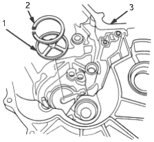
- 1. OIL GUIDE PLATE
- 2. 78 mm SHIM
- 3. TRANSMISSION
- -2.
Install the spring washer and washer on the ball bearing.
NOTE:
- Clean the spring washer, washer and thrust shim thoroughly before installation.
- Install the spring washer, washer and thrust shim properly.
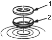
- 1. WASHER
- 2. SPRING WASHER
- -3.Install the mainshaft in the clutch housing.
- -4.Place the transmission housing over the mainshaft and onto the clutch housing.
- -5.
Tighten the clutch and transmission housings with several 8 mm bolts.
NOTE: It is not necessary to use sealing agent between the housings.
- -6.Tap the mainshaft with a plastic hammer.
PDF p. 544 · 13-70
- -7.Slide the mainshaft base over the mainshaft.
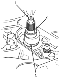
- 1. MAINSHAFT
- 2. CLUTCH HOUSING
- 3. MAINSHAFT BASE, 07GAJ-PG20130
- -8.
Attach the mainshaft holder to the mainshaft as follows:
NOTE:
- Back-out the mainshaft holder bolt and loosen the two hex. bolts.
- Fit the holder over the mainshaft so its lip is towards the transmission.
- Align the mainshaft holder’s lip around the groove at the inside of the mainshaft splines, then tighten the hex bolts.
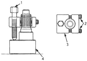
- 1. MAINSHAFT HOLDER BOLT
- 2. HEX BOLTS
- 3. MAINSHAFT HOLDER, 07GAJ-PG20110
- 4. MAINSHAFT BASE, 07GAJ-PG20130
- -9.Seat the mainshaft fully by tapping its end with a plastic hammer.
- -10.Thread the mainshaft holder bolt in until it just contacts the wide surface of the mainshaft base.
- -11.Zero a dial gauge on the end of the mainshaft.
- -12.Turn the mainshaft holder bolt clockwise; stop turning when the dial gauge has reached its maximum movement. The reading on the dial gauge is the amount of mainshaft end play.
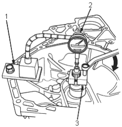
- 1. MAGNET STAND BASE, 07979-PJ40001
- 2. DIAL GAUGE
- 3. MAINSHAFT HOLDER, 07GAJ-PG20110
- -13.
If the reading is within the standard, the clearance is correct.
If the reading is not within the standard, recheck the shim thickness.
Standard: 0.11 - 0.18 mm (0.004 - 0.007 in)