PDF p. 511 · 13-37
NOTE: For reassembly sequence (See page 13-32).
- 1.
Install the thrust shim, needle bearing, 1st gear and friction damper.
NOTE: Reassemble the friction damper on the 1st gear before installation.
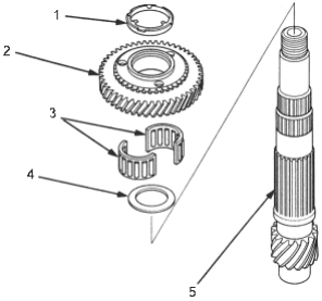
- 1. FRICTION DAMPER
- 2. 1ST GEAR
- 3. NEEDLE BEARING
- 4. THRUST SHIM
- 5. COUNTERSHAFT
- 2.Install the double cone synchro.
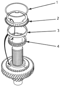
- 1. SYNCHRO SPRING
- 2. OUTER SYNCHRO RING
- 3. SYNCHRO CONE
- 4. INNER SYNCHRO RING
- 3.Install the 1st/2nd synchro hub by aligning the friction damper fingers with 1st/2nd synchro hub grooves.
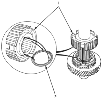
- 1. 1ST/2ND SYNCHRO HUB
- 2. FRICTION DAMPER
PDF p. 512 · 13-38
- 4.Reassemble the friction damper on the spacer using the special tools and a press as shown.
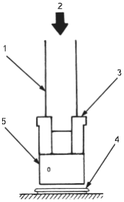
- 1. HANDLE DRIVER, 07749-0010000
- 2. PRESS
- 3. DRIVER ATTACHMENT, 42 x 47 mm, 07746-0010300
- 4. FRICTION DAMPER
Inspect for wear and damage - 5. SPACER
- 5.Install the 2nd gear by aligning the synchro cone fingers with the 2nd gear grooves.
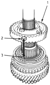
- 1. 2ND GEAR
- 2. GROOVE
- 3. FINGER
- 6.Support the countershaft on a steel block as shown and install 3rd gear using the special tools and a press as shown.
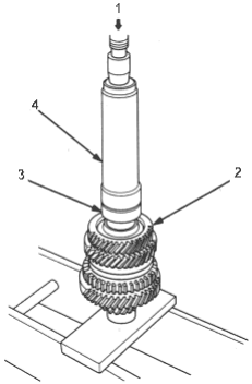
- 1. PRESS
- 2. 3RD GEAR
- 3. ATTACHMENT, 35 mm I.D., 07746-0030400
- 4. DRIVER, 40 mm I.D., 07746-0030100
- 7.Install 4th gear using the special tools and a press as shown.
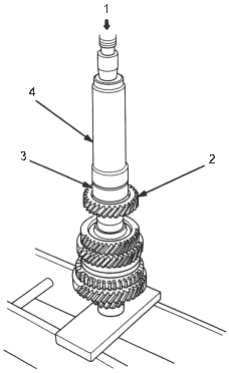
- 1. PRESS
- 2. 4TH GEAR
- 3. ATTACHMENT, 35 mm I.D., 07746-0030400
- 4. DRIVER, 40 mm I.D., 07746-0030100
PDF p. 513 · 13-39
- 8.Install 5th gear using the special tools and a press as shown.
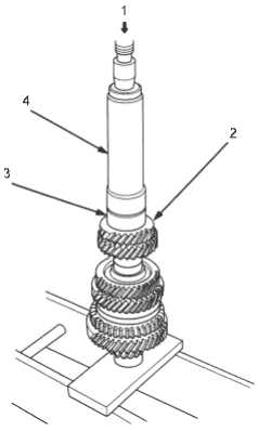
- 1. PRESS
- 2. 5TH GEAR
- 3. ATTACHMENT, 30 mm I.D. 07746-0030300
- 4. DRIVER, 40 mm I.D., 07746-030300
- 9.Install the needle bearing using the special tools and a press as shown and install the bearing outer race.
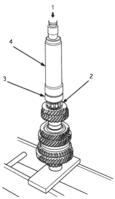
- 1. PRESS
- 2. NEEDLE BEARING
- 3. ATTACHMENT, 30 mm I.D., 07746-0030300
- 4. DRIVER, 40 mm I.D., 07746-0030010
- 10.Install the ball bearing using the special tools and a press as shown.
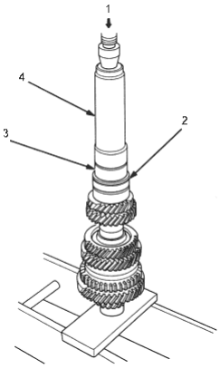
- 1. PRESS
- 2. BALL BEARING
- 3. ATTACHMENT, 30 mm I.D., 07746-0030300
- 4. DRIVER, 40 mm I.D., 07746-0030010
- 11.Securely clamp the countershaft assembly in a bench vice with wood blocks.
- 12.Install the spring washer.
- 13.
Install the new locknut to the correct torque, then stake the locknut tab into the groove.
Torque: 127 to 0 to 127 Nm
(13 to 0 to 13 kgf/m,
94 to 0 to 94 lbf/ft)
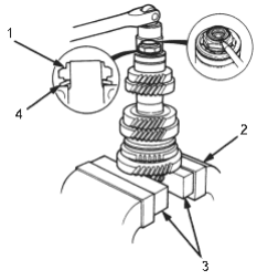
- 1. LOCKNUT, Replace
- 2. BENCH VICE
- 3. WOOD BLOCKS
- 4. SPRING WASHER