PDF p. 509 · 13-35
- 1.Securely clamp the countershaft assembly in a bench vice with wood blocks.
- 2.Raise the locknut tab from the groove in the countershaft, then remove the locknut and the spring washer.
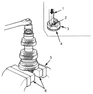
- 1. CHISEL
- 2. TAB
- 3. LOCKNUT, Replace
- 4. SPRING WASHER
- 5. BENCH VICE
- 6. WOOD BLOCKS
- 3.Remove the ball bearing using a press as shown.
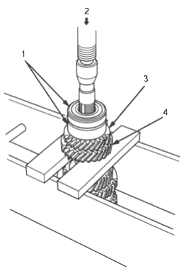
- 1. BEARINGS
- 2. PRESS
- 3. 5TH GEAR
- 4. 4TH GEAR
- 4.Remove the friction damper from the spacer using a press and a socket as shown.
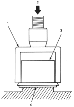
- 1. SOCKET
- 2. PRESS
- 3. SPACER
- 4. FRICTION DAMPER Inspect for wear and damage
- 5.Support 1st gear on steel blocks and press the countershaft out of 3rd gear as shown.
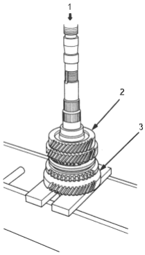
- 1. PRESS
- 2. 3RD GEAR
- 3. 1ST GEAR