PDF p. 470 · 12-12
- 1.Inspect the ring gear teeth for wear and damage.
- 2.Inspect the clutch disc mating surface on the flywheel for wear, cracks and burning.
- 3.
Measure the flywheel runout using a dial indicator through at least two full turns. Push against the flywheel each time you turn it to take up the crankshaft thrust washer clearance.
NOTE: The runout can be measured with engine installed.
Standard (New): 0.05 mm (0.002 in) max. Service Limit: 0.15 mm (0.006 in) If the runout is more than the service limit, replace the flywheel and recheck the runout.
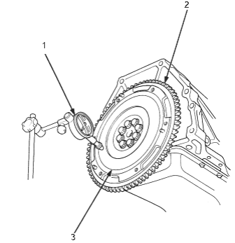
- 1. DIAL INDICATOR
- 2. RING GEAR
- 3. FLYWHEEL
Replacement
- 1.Install the special tool as shown.
- 2.Remove the flywheel mounting bolts in a crisscross pattern in several steps, and remove the flywheel.
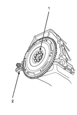
- 1. 12 x 1.0 mm, 103 Nm (10.5 kgf/m, 75.9 lbf/ft)
- 2. RING GEAR HOLDER, 07LAB-PV00100 or 07924-PD20003
- 3.Install the flywheel in reverse order of removal.