PDF p. 467 · 12-10
- 1.
Check the diaphragm spring fingers for height using the dial indicator.
Standard (New): 0.6 mm (0.02 in) max Service Limit: 0.8 mm (0.03 in)
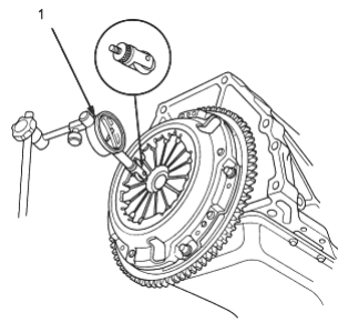
- 1. DIAL INDICATOR
If the height is more than the service limit, replace the pressure plate.
- 2.Install the special tools as shown.
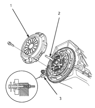
- 1. PRESSURE PLATE
- 2. CLUTCH ALIGNMENT TOOL SET, 07PAF-0020000
- 3. RING GEAR HOLDER, 07LAB-PV00100 or 07924-PD20003
- 3.To prevent warping, unscrew the pressure plate mounting bolts in a crisscross pattern in several steps, then remove the pressure plate.
- 4.Inspect the fingers of the diaphragm spring for wear at the release bearing contact area.
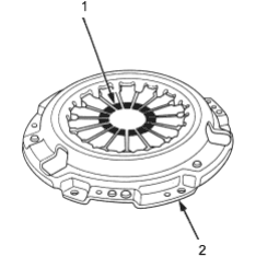
- 1. DIAPHRAGM SPRING
- 2. PRESSURE PLATE
- 5.Inspect the pressure plate surface for wear, cracks and burning.
- 6.
Inspect for warpage using a straight edge and feeler gauge.
Standard (New): 0.03 mm (0.001 in) max Service Limit: 0.15 mm (0.006 in)
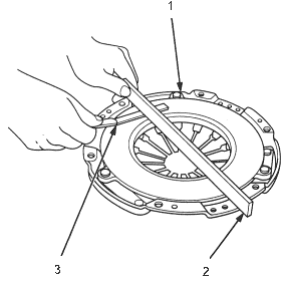
- 1. PRESSURE PLATE
- 2. STRAIGHT EDGE
- 3. FEELER GAUGE
If the warpage is more than the service limit replace the pressure plate.