PDF p. 292 · 7-22
OIL Before installing the piston, apply a coat of engine oil
to the ring grooves and cylinder bores.
- 1.If the crankshaft is already installed:
- Set the crankshaft to BDC for each cylinder.
- Remove the connecting rod caps and slip short sections of rubber hose over the threaded ends of the connecting rod bolts.
- Install the ring compressor, check that the bearing is securely in place, then position the piston in the cylinder and tap it in using the wooden handle of a hammer.
- Stop after the ring compressor pops free and check the connecting rod-to-journal alignment before pushing piston into place.
Install the rod caps with bearings and torque the nuts to:
31 Nm (3.2 kgf/m (23 lbf/ft)
Apply engine oil to the bolt threads.
2.
If the crankshaft is not installed:
- Remove the rod caps and bearings, install the ring compressor, then position the piston in the cylinder and tap it in using the wooden handle of a hammer.
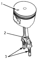
- 1. The arrow must face the timing belt side of the engine.
- 2. CONNECTING ROD OIL HOLE
- 3. RUBBER HOSES
- Position all pistons at top dead centre.
NOTE: Maintain downward force on the ring compressor to prevent rings from expanding before entering the cylinder bore.
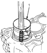
- 1. RING COMPRESSOR
Crankshaft
Installation
OIL Before installing the crankshaft, apply a coat of
engine oil the main bearings and rod bearings.
- 1.Insert the thrust washers in the No. 4 journal of the cylinder block.
- 2.Insert bearing halves in the cylinder block and connecting rods.
- 3.Hold the crankshaft so rod journals for cylinders No. 2 and No. 3 are straight down.
- 4.Lower the crankshaft into the block, seating the rod journals into connecting rods No. 2 and No. 3 and install the rod caps and nuts finger-tight.
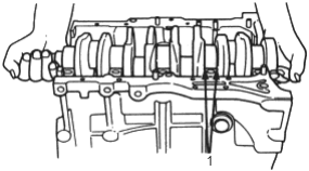
- 1. THRUST WASHER. Grooved sides face outward.
- 5.
Rotate the crankshaft clockwise, seat journals into connecting rods No. 1 and No. 4 and install the rod caps and nuts finger-tight.
NOTE: Install caps so the bearing recess is on the same side as the recess in the rod.