PDF p. 289 · 7-19
End Gap
- 1.Using a piston, push a new ring into the cylinder bore 15 - 20 mm (0.6 - 0.8 in) from the bottom.
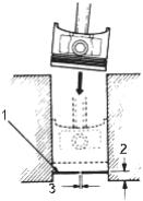
- 1. PISTON RING
- 2. 15 - 20 mm (0.6 - 0.8 in)
- 3. END GAP
- 2.Measure the piston ring end-gap with a feeler gauge:
- If the gap is too small, check to see if you have the proper rings for your engine.
- If the gap is too large, recheck the cylinder bore diameter against the wear limits on page 7-15. If the bore is over the service limit, the cylinder block must be rebored.
Piston Ring End-Gap:
Top Ring
Standard (New): 0.15 - 0.30 mm
(0.006 - 0.012 in)
Service Limit: 0.60 mm (0.025 in) Second Ring
Standard (New):
Service Limit:
Oil Ring
D16W1 engine:
Standard (New):
Service Limit:
D16W2 engine:
Standard (New):
Service Limit:
0.30 - 0.45 mm (0.012 - 0.018 in) 0.70 mm (0.028 in)
0.20 - 0.70 mm (0.008 - 0.028 in) 0.80 mm (0.031 in)
0.20 - 0.80 mm (0.008 - 0.032 in) 0.90 mm (0.035 in)
Replacement
- 1.Using a ring expander, remove the old piston rings.
- 2.
Clean all ring grooves thoroughly.
NOTE:
- Use a squared-off broken ring or ring groove cleaner with blade to fit piston grooves.
- Top ring groove is 1.0 mm (0.039 in) wide (D16W1 engine) or 1.2 mm (0.047 in) wide (D16W2 engine).
- Second ring groove is 1.2 mm (0.047 in) wide (D16W1 engine) or 1.5 mm (0.059 in) wide (D16W2 engine).
- Oil ring groove is 2.8 mm (0.11 in) wide.
- File down blade if necessary.
- Do not use a wire brush to clean ring lands, or cut ring lands deeper with cleaning tool.
- 3.
Install new rings in proper sequence and position (See Page 7-21).
NOTE:
- Do not reuse old piston rings.
- If piston is to be separated from connecting rod, do not install new rings yet.
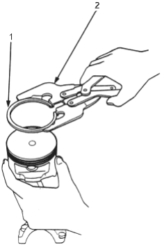
- 1. PISTON RING
- 2. RING EXPANDER
PDF p. 290 · 7-20
Ring-to-Groove Clearance
After installing a new set of rings, measure ring-to-groove clearances:
Top Ring Clearance
D16W1 engine:
| Standard (New): | 0.035 - 0.060 mm (0.0014 - 0.0024 in) |
| Service limit: | 0.13 mm (0.005 in) |
| D16W2 engine: | |
| Standard (New): | 0.030 - 0.060 mm (0.0012 - 0.0024 in) |
| Service Limit: | 0.13 mm (0.005 in) |
| Second Ring Clearance | |
| Standard (New): | 0.030 - 0.055 mm (0.0012 - 0.0022 in) |
| Service Limit: | 0.13 mm (0.005 in) |
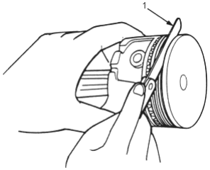
- 1. FEELER GAUGE
Alignment
- 1.
Install the rings as shown.
NOTE: The manufacturing marks must be facing upwards.
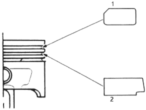
- 1. TOP RING
- 2. SECOND RING
Piston Ring Dimensions:
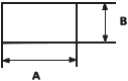
Top Ring (Standard) Unit mm (in)
| A | B | |
| D16W1 engine | 2.6 (0.10) | 1.0 (0.04) |
| D16W2 engine | 2.8 (0.11) | 1.2 (0.05) |
Second Ring (Standard) Unit mm (in)
| A | B | |
| D16W1 engine | 3.0 (0.12) | 1.2 (0.05) |
| D16W2 engine | 3.2 (0.13) | 1.5 (0.06) |
PDF p. 291 · 7-21
- 2.Rotate the rings in their grooves to make sure they do not bind.
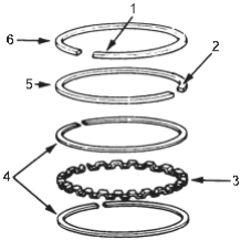
- 1. MARK
- 2. MARK
- 3. SPACER
- 4. OIL RING
- 5. SECOND RING
- 6. TOP RING
- 3.Position the ring end gaps as shown.
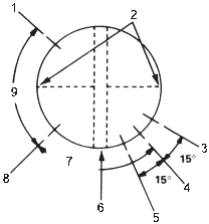
- 1. SECOND RING GAP
- 2. DO NOT position any ring gap at piston thrust surfaces.
- 3. OIL RING GAP
- 4. SPACER GAP
- 5. OIL RING GAP
- 6. DO NOT position any ring gap in line with the piston pin hole.
- 7. Approx. 90°
- 8. TOP RING GAP
- 9. Approx. 90°
Crankshaft Oil Seal
Installation
OIL The seal surface on the block should be dry.
Apply a light coat of oil to the crankshaft and to the tip of the seal.
- 1.
Drive in crankshaft oil seal against right side cover.
NOTE: Drive the crankshaft oil seal in squarely.
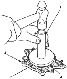
- 1. HANDLE DRIVER, 07749-0010000
- 2. Install seal with the part number side facing out.
- 3. DRIVER ATTACHMENT, 96 mm, 07948-SB00101
- 4. RIGHT SIDE COVER.
- 2.
Confirm that the clearance is equal all the way around with a feeler gauge.
Clearance: 0.5 - 0.8 mm (0.02 - 0.03 in)
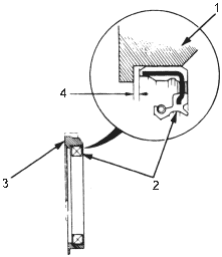
- 1. RIGHT SIDE COVER
- 2. CRANKSHAFT OIL SEAL
- 3. RIGHT SIDE COVER
- 4. 0.5 - 0.8 mm (0.02 - 0.03 in)
NOTE: (See page 8-11) for installation of the oil pump side crankshaft oil seal.