PDF p. 287 · 7-17
Each rod falls into one of four tolerance ranges (from 0 to + 0.024 mm (0 to + 0.0009 in) in 0.006 mm (0.0002 in) increments) depending on the size of its big end bore. It’s then stamped with a number (1, 2, 3, or 4) indicating the range.
You may find any combination of 1, 2, 3, or 4 in any engine. Normal Bore Size: 48.0 mm (1.89 in)
NOTE:
- Reference numbers are for big end bore size and do NOT indicate the position of the rod in the engine.
- Inspect connecting rod for cracks and heat damage.
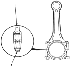
- 1. CONNECTING ROD BORE REFERENCE NUMBER.
Half of number is stamped on the bearing cap, the other half on the connecting rod. - 2. Inspect bolts and nuts for stress cracks.
Piston Pins
Installation
NOTE:
- Use the piston pin assembly tool set (No. 07PAF-010000) with a hydraulic press.
- Be sure to use the pilot collar of correct No. as designated.
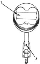
- 1. The arrow must face the timing belt side of the engine and the engine and the connecting rod oil hole must face the rear of the engine.
- 2. CONNECTING ROD OIL HOLE
- 1.Install the piston pin as shown.
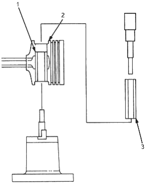
- 1. PILOT COLLAR, O.D. 19 mm, 07PAF-0010650
- 2. Embossed mark facing up.
- 3. PISTON PIN
NOTE: Install the assembled piston and rod with the oil hole facing the intake manifold.