PDF p. 281 · 7-11
- 1.Removal the oil pan assembly.
- 2.Remove the right side cover.
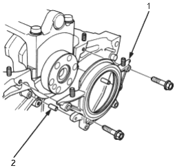
- 1. RIGHT SIDE COVER
- 2. DOWEL PIN
- 3.Remove the oil screen.
- 4.Remove the oil pump.
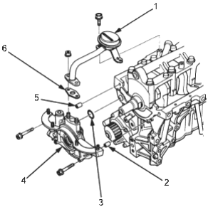
- 1. OIL SCREEN
- 2. DOWEL PIN
- 3. O-RING. Replace.
- 4. OIL PUMP
- 5. DOWEL PIN
- 6. GASKET. Replace.
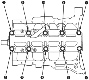
- 5.Remove the bolts. To prevent warpage, unscrew the bolt in sequence 1/3 turn at a time; repeat the sequence until all bolts are loosened, then remove the bearing cap.
MAIN BEARING CAP BOLTS LOOSENING
SEQUENCE
- 6.Remove the rod caps/bearings and main caps/bearings. Keep all caps/bearings in order.
- 7.Lift the crankshaft out of the engine, being careful not to damage the bearings.
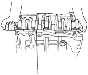
- 1. CRANKSHAFT
PDF p. 282 · 7-12
- 8.Remove the upper bearing halves from the connecting rods and set them aside with their respective caps.
- 9.Reinstall the main caps and bearings on the engine in the proper order.
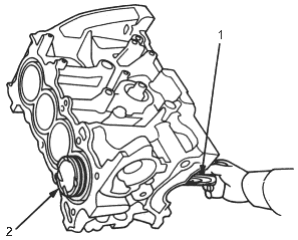
- 10.If you can feel a ridge of metal or hard carbon around the top of each cylinder, remove it with a ridge reamer. Follow the reamer manufacturer’s instructions. If the ridge is not removed, it may damage the pistons as they are pushed out.
- 1. RIDGE REAMER
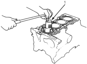
- 11.Use the wooden handle of a hammer to drive the pistons out.
- 1. HAMMER HANDLE
- 2. PISTON
- 12.Reinstall the connecting rod bearings and caps after removing each piston/connecting rod assembly.
- 13.
Mark each piston/connecting rod assembly with its cylinder number to avoid mix-up on assembly.
NOTE: The existing number on the connecting rod does not indicate its position in the engine, it indicates the rod bore size.