PDF p. 276 · 7-6
Manual Transmission
Remove the six flywheel bolts, then separate the flywheel from the crankshaft flange. After installation, tighten the bolts in a criss-cross pattern.
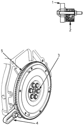
- 1. RING GEAR HOLDER, 07LAB-PV00100
- 2. ENGINE BLOCK
- 3. 12 X 1.0 mm, 118 Nm (12.0 kgf/m, 87 lbf/ft)
- 4. RING GEAR HOLDER, 07LAB-PV00100
- 5. RING GEAR. Inspect ring gear teeth of wear or damage.
Automatic Transmission
Remove the six drive plate bolts, then separate the drive plate from the crankshaft flange. After installation, tighten the bolts in a criss-cross pattern.
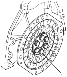
- 1. 12 x 1.0 mm, 74 Nm (7.5 kgf/m, 54 lbf/ft)