PDF p. 273 · 7-3
NOTE:
Apply liquid gasket to the mating surfaces of the right side cover and oil pump housing before installing them. Use liquid gasket part No. 08C70-K0234M, 08C70-K0334M or, 08C70-X0331S.
Clean the oil pan gasket mating surfaces before installing it.
OIL Lubricate all internal parts with engine oil during reassembly.
Europe, Australia and South Africa models:
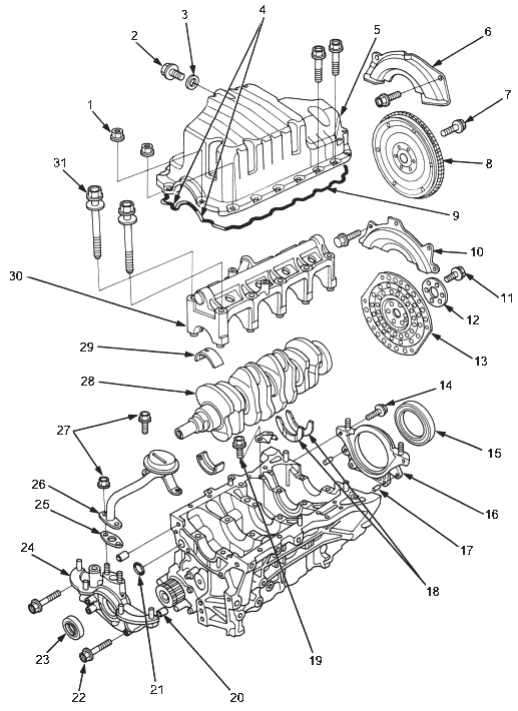
- 1. 6 x 1.0 mm, 12 Nm (1.2 kgf/m, 8.7 lbf/ft)
- 2. DRAIN BOLT, 39 Nm (4.0 kgf/ft, 29 lbf/ft)
- 3. WASHER. Replace.
- 4. Apply liquid gasket to these points.
- 5. OIL PAN. Installation (see page 7-25).
- 6. FLYWHEEL COVER (M/T)
- 7. 12 x 1.0 mm, 118 Nm (12.0 kgf/m, 87 lbf/ft)
- 8. FLYWHEEL (M/T)
- 9. OIL PAN GASKET. Replace.
- 10. DRIVE PLATE COVER (CVT)
- 11. 12 X 1.0 MM, 74 Nm (7.5 kgf/m, 54 lbf/ft)
- 12. WASHER
- 13. DRIVE PLATE (CVT). Check for cracks.
- 14. 6 x 1.0 mm, 11 Nm (1.1 kgf/m, 8.0 lbf/ft)
- 15. CRANKSHAFT OIL SEAL. Installation, (see page 7-21). Replace.
- 16. RIGHT SIDE COVER. Apply liquid gasket to mating surface.
- 17. DOWEL PIN
- 18. THRUST WASHERS. Grooved sides face outward.
NOTE: Thrust washer thickness is fixed and must not be changed by grinding or shimming. - 19. BREATHING PORT COVER MOUNT BOLTS, 6 x 1.0 mm, 11 Nm (1.1 kgf/m, 8.0 lbf/ft). Apply liquid gasket to the bolt threads.
- 20. DOWEL PIN
- 21. O-RING. Replace
- 22. 6 x 1.0 mm, 11 Nm (1.1 kgf/m, 8.0 lbf/ft)
- 23. CRANKSHAFT. Installation, (see page 8-11). Replace.
- 24. OIL PUMP. Overhaul, (see page 8-9). Removal/Inspection, (see page 8-10). Apply liquid gasket to mating surface.
- 25. GASKET. Replace.
- 26. OIL SCREEN
- 27. 6 x 1.0 mm, 11 Nm (1.1 kgf/m, 8.0 lbf/ft)
- 28. CRANKSHAFT. Installation, (see page 7-13).
- 29. MAIN BEARINGS. Selection, (see page 7-9).
NOTE: New main bearings must be selected by matching crank and block identification markings. - 30. MAIN BEARING CAP
- 31. 11 x 1.5 mm, 51 Nm (5.2 kgf/m, 38 lbf/ft). Apply engine oil to the bolt threads.
NOTE: After torquing each cap, turn crankshaft to check for binding.
PDF p. 274 · 7-4
Except Europe, Australia and South Africa models:
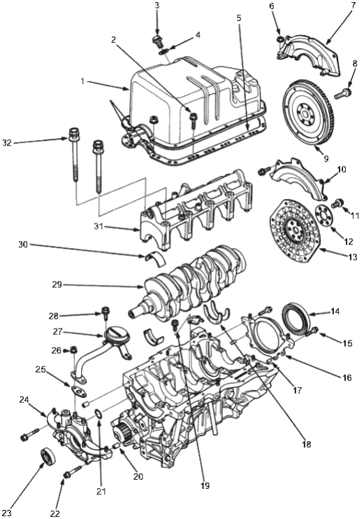
- 1. OIL PAN. Installation (see page 7-26).
- 2. 6 x 1.0 mm, 12 Nm ( 1.2 kgf/m, 8.7 lbf/ft)
- 3. DRAIN BOLT, 44 Nm (4.5 kgf/m, 33 lbf/ft)
- 4. WASHER. Replace.
- 5. OIL PAN GASKET. Replace.
- 6. 6 x 1.0, 12 Nm (1.2 kgf/m, 8.7 lbf/ft)
- 7. FLYWHEEL COVER (M/T)
- 8. 12 x 1.0 mm, 118 Nm (12.0 kgf/m, 87 lbf/ft)
- 9. FLYWHEEL (M/T)
- 10. DRIVE PLATE COVER (A/T)
- 11. 12 x 1.0 mm, 74 Nm (7.5 kgf/m, 54 lbf/ft)
- 12. WASHER
- 13. DRIVE PLATE (CVT). Check for cracks.
- 14. CRANKSHAFT OIL SEAL. Installation (see page 7-21). Replace.
- 15. 6 x 1.0 mm, 11 Nm (1.1 kgf/m, 8.0 lbf/ft)
- 16. RIGHT SIDE COVER. Apply liquid gasket to mating surface.
- 17. DOWEL PIN
- 18. THRUST WASHERS. Grooved sides face outward.
NOTE: Thrust washer thickness is fixed and must not be changed by grinding or shimming. - 19. BREATHING PORT COVER MOUNT BOLTS. 6 x 1.0 mm, 11 Nm (1.1 kgf/m, 8.0 lbf/ft). Apply liquid gasket to the bolt threads.
- 20. DOWEL PIN
- 21. O-RING. Replace.
- 22. 6 x 1.0 mm, 11 Nm (1.1 kgf/m, 8.0 lbf/ft)
- 23. CRANKSHAFT SEAL. Installation (see page 8-11). Replace.
- 24. OIL PUMP. Overhaul (see page 8-9). Removal/Inspection (see page 8-10). Apply liquid gasket to mating surface.
- 25. GASKET. Replace
26 6 x 1.0 mm, 11 Nm (1.1 kgf/m, 8.0 lbf/ft) - 27. OIL SCREEN
- 28. 6 x 1.0 mm, 11 Nm, (1.1 kgf/m, 8.0 lbf/ft)
- 29. CRANKSHAFT. Installation (see page 7-13).
- 30. MAIN BEARINGS. Selection (see page 7-9).
NOTE: New main bearings must be selected by matching crank and block identification markings. - 31. MAIN BEARING CAP
- 32. 11 x 1.5 mm, 51 Nm (5.2 kgf/m, 38 lbf/ft). Apply engine oil to the bolt threads.
NOTE: After torquing each cap, turn crankshaft to check for binding.
PDF p. 275 · 7-5
NOTE: New rod bearings must be selected by matching connecting rod assembly and crankshaft identification markings (see page 7-10).
OIL Lubricate all internal parts with engine oil during reassembly.
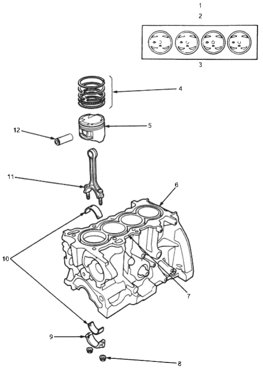
- 1. PISTON INSTALLATION DIRECTION
- 2. EXHAUST
- 3. INTAKE
- 4. PISTON RINGS
Replacement (see page 7-19). Measurement (see page 7-19) Alignment (see page 7-20) - 5. PISTON
Inspection (see page 7-14)
NOTE: Before removing pistons, inspect the top of the cylinder bore for carbon build-up or ridge. Remove the ridge if necessary, (see page 7-12) - 6. ENGINE BLOCK
Cylinder bore inspection, (see page 7-15)
Warpage inspection, (see page 7-15) Cylinder bore honing, (see page 7-16) - 7. Inspect top of each cylinder bore for carbon build-up or ridge before removing piston. Remove ridge if necessary, (see page 7-12)
- 8. CONNECTING ROD CAP NUT, 8x 0.75 mm, 31 Nm (3.2 kgf/m, 23 lbf/ft). Apply engine oil to the nut threads. NOTE: After torquing each bearing cap, rotate crankshaft to check for binding.
- 9. CONNECTING ROD BEARING CAP. Installation, (see page 7-22)
NOTE: Install caps so the bearing recess is on the same side as the recess in the rod. - 10. CONNECTING ROD BEARINGS. Clearance, (see page 7-10) Selection, (see page 7-10)
- 11. CONNECTING ROD
End play, (see page 7-7)
Selection, (see page 7-17) - 12. PISTON PIN
Removal, (see page 7-16) Installation, (see page 7-17) Inspection, (see page 7-18)