PDF p. 267 · 6-28
NOTE:
- Make sure that all rockers are in alignment with valves when torquing rocker assembly bolts.
- Valve locknuts should be loosened and adjusting screws backed off before installation.
- To prevent rocker arm assembly from coming apart, leave camshaft holder bolts in the holes.
- 1.After wiping down the camshaft, camshaft seal and journals in the cylinder head, lubricate both surfaces and install the camshaft.
- 2.Clean and install the oil control orifice with new O-ring.
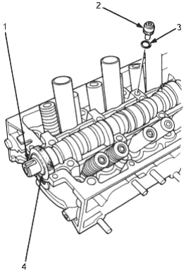
- 1. CAMSHAFT. Keyway up.
- 2. OIL CONTROL ORIFICE. Clean.
- 3. O-RING. Replace.
- 4. CAMSHAFT SEAL. Seal housing should be dry. Apply a light coat of oil to camshaft and inner lip of seal.
- 3.Turn the camshaft until its keyway is facing up (No. 1 piston TDC).
- 4.
Apply liquid gasket (P/N 08C70 - K0234M, 08C70 - K0334M, or 08C70 - X0331S) to the head mating surfaces of the No. 1 and No. 5 camshaft holders.
NOTE: Clean and dry the cylinder head mating surfaces before applying liquid gasket.
- Apply liquid gasket to the shaded areas.
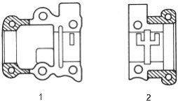
- 1. No. 5
- 2. No. 1
- 5.Set the rocker arm assembly in place and loosely install the bolts.
- Make sure that the rocker arms are properly positioned on the valve stems.
- 6.
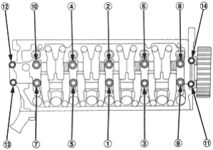
Tighten each bolt two turns at a time in the sequence shown below to ensure that the rockers do not bind on the valves.
NOTE: Wipe off the excess of liquid gasket from No. 1 and No. 5 camshaft holders with a shop towel.
Specified torque:
8 mm bolts: 20 Nm (2.0 kgf/m, 14 lbf/ft)
Apply engine oil to the threads.
6 mm bolts: 12 Nm (1.2 kgf/m, 8.7 lbf/ft)
6 mm bolts: 11, 12, 13, 14
PDF p. 268 · 6-29
- 7.Install the back cover, then install the camshaft pulley.
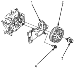
- 1. BACK COVER
- 2. CAMSHAFT PULLEY. Clean when installing.
- 3. 8 x 1.25 mm, 37 Nm (3.8 kgf/m, 27 lbf/ft). Apply engine oil to the bolts threads.
- 4. 6 x 1.0 mm, 12 Nm (1.2 kgf/m, 8.7 lbf/ft)
Cylinder Head
Installation
Install the cylinder head in the reverse order of removal:
NOTE:
- Always use a new head gasket.
- Cylinder head and cylinder block surface must be clean.
- “UP” mark on camshaft pulley should be at the top.
- Turn the crankshaft so the No. 1 piston is at TDC (see page 6-10).
- Clean the oil control orifice before installing.
- Do not use the upper cover and lower cover for storing items disassembled.
- Clean the upper cover and lower cover before installation.
- 1.Cylinder head dowel pins must be aligned.
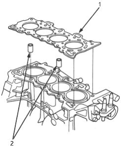
- 1. CYLINDER HEAD GASKET
- 2. DOWEL PINS