PDF p. 247 · 6-8
NOTE:
- Turn the crankshaft pulley so the No. 1 piston is at top dead centre (TDC) before removing the belt (see page 6-11).
- Inspect the water pump before installing the timing belt (see page 10-11)
- 1.Remove the splash shield (see page 5-7).
- 2.Remove the intake air duct B (see page 5-3).
- 3.Remove the breather hose, then remove the air cleaner housing (see page 5-4).
- 4.Disconnect the intake air temperature (IAT) sensor connector, then remove the intake air duct (see page 5-4).
- 5.Loosen the mounting bolt and lock bolt, then remove the power steering (P/S) pump belt.
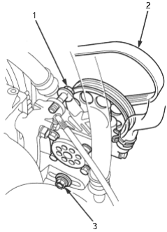
- 1. MOUNTING BOLT, 8 x 1.25 mm, 24 Nm (2.4 kgf/m, 17 lbf/ft)
- 2. P/S PUMP BELT
- 3. LOCK BOLT, 8 x 1.25 mm, 24 Nm (2.4 kgf/m, 17 lbf/ft)
- 6.Loosen the idler pulley centre nut and adjusting bolt, then remove the air conditioning (A/C) compressor belt (see page 5-4).
- 7.Loosen the mounting nut and lock bolt, then remove the alternator belt.
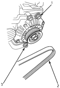
- 1. LOCK BOLT, 8 x 1.25 mm, 24 Nm (2.4 kgf/m, 17 lbf/ft)
- 2. ALTERNATOR BELT
- 3. MOUNTING NUT, 10 x 1.25 mm, 44 Nm (4.5 kgf/m, 33 lbf/ft)
- 8.Remove the engine mount bracket A.
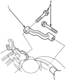
- 1. ENGINE MOUNT BRACKET A
- 2. 10 x 1.25 mm, 44 Nm (4.5 kgf/m, 33 lbf/ft)
PDF p. 248 · 6-9
- 9.Support the engine with the jack and wood block under the oil pan.
- 10.Remove the side engine mount.
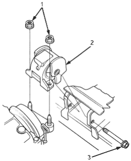
- 1. 12 x 1.25 mm, 74 Nm (7.5 kgf/m, 54 lbf/ft)
- 2. SIDE ENGINE MOUNT
- 3. 12 x 1.25 mm, 74 Nm (7.5 kgf/m, 54 lbf/ft)
- 11.
Remove the dipstick, then remove the upper cover and idler pulley bracket.
NOTE: Do not use the upper cover for storing removed items.
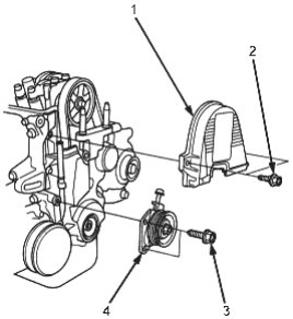
- 1. UPPER COVER
- 2. 6 x 1.0 mm, 9.8 Nm (1.0 kgf/m, 7.2 lbf/ft)
- 3. 8 x 1.25 mm, 24 Nm (2.4 kgf/m, 17 lbf/ft)
- 4. IDLER PULLEY BRACKET
- 12.
Remove the dipstick tube and lower cover.
NOTE: Do not use the upper cover for storing removed items.
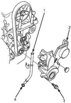
- 1. DIPSTICK TUBE
- 2. LOWER COVER
- 3. 6 x 1.0 mm, 9.8 Nm (1.0 kgf/m, 7.2 lbf/ft)
- 4. O-RING, Replace
- 13.Loosen the adjustment bolt 180°. Push the tensioner to remove tension from the timing belt, then retighten the adjusting bolt. .
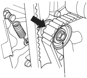
- 1. ADJUSTING BOLT, 44 Nm (4.5 kgf/m, 33 lbf/ft)
- 14.Remove the timing belt.