PDF p. 2054 · 24-2
SRS components are located in this area. Review the SRS component locations, precautions and procedures in the 1999 HR-V Shop Manual, P/N. 62S2H00, before performing repairs or service.
NOTE: Check the front seat belts for damage, and replace them if necessary. Be careful not to damage them during removal and installation.
Front seat belt (5D):
- 1.Disconnect the negative battery cable, and wait at least three minutes before beginning work.
- 2.Slide the front seat all the way around.
- 3.Remove (see section 20):
- Front side trim
- Rear side trim
- Centre pillar lower trim
- 4.Remove the upper anchor cover, and pull the lower anchor cover back.
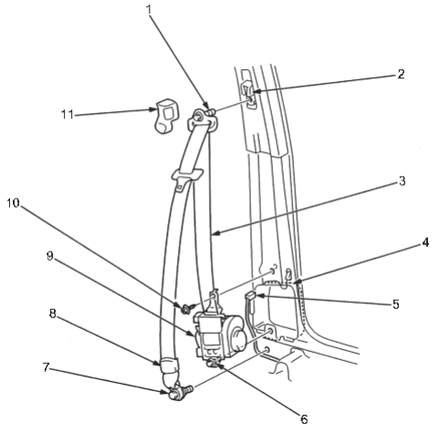
- 1. UPPER ANCHOR BOLT 7/16-20UNF 32 Nm (3.3 kgf/m, 24 lbf/ft)
- 2. SHOULDER ANCHOR ADJUSTER
- 3. FRONT SEAT BELT
- 4. RETRACTOR PROTECTOR
- 5. SEAT BELT TENSIONER
CONNECTOR - 6. RETRACTOR BOLT 7/16-20UNF
32 Nm (3.3 kgf/m, 24 lbf/ft) - 7. LOWER ANCHOR BOLT 7/16-20UNF 32 Nm (3.3 kgf/m, 24 lbf/ft)
- 8. LOWER ANCHOR COVER
- 9. RETRACTOR
- 10. RETRACTOR MOUNTING SCREW
6 x 1.0 mm 4Nm (0.4 kgf/m, 3 lbf/ft) - 11. UPPER ANCHOR COVER
- 5.Disconnect the seat belt tensioner connector.
- 6.Remove the upper anchor bolt and lower anchor bolt, the retractor mounting screw, and the retractor bolt, and remove the front seat belt and retractor.
PDF p. 2055 · 24-3
- 7.Remove the front and rear door trim as necessary (see section 20).
- 8.Remove the centre pillar upper trim (see section 20).
- 9.Remove the shoulder anchor adjuster.
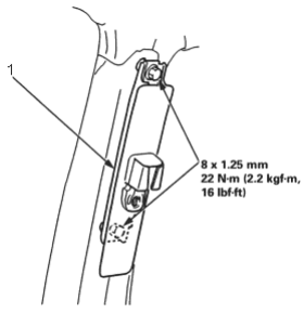
- 1. SHOULDER ANCHOR ADJUSTER
- 10.Install in the reverse order of removal, and note these items:
- If the threads on the retractor mounting screw are worn out, use an oversized screw made specifically for this application.
- Check that the retractor locking mechanism functions as described (See Page 24-6).
- Assemble the washers, collar and bushing on the upper and lower anchor bolts as shown.
- Before installing the anchor bolts, make sure there are no twists or kinks in the front seat belt.
- Make sure the seat belt tensioner connector is plugged in properly.
Upper anchor bolt construction:
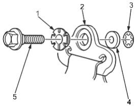
- 1. BUSHING
- 2. UPPER ANCHOR
- 3. TOOTHED LOCK WASHER
- 4. COLLAR
- 5. UPPER ANCHOR BOLT
Lower anchor bolt construction:
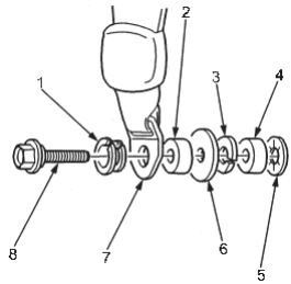
- 1. BUSHING
- 2. COLLAR
- 3. SPRING WASHER
- 4. COLLAR
- 5. TOOTHED LOCK WASHER
- 6. WASHER
- 7. LOWER ANCHOR
- 8. LOWER ANCHOR BOLT
Retractor bolt construction:
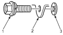
- 1. RETRACTOR BOLT
- 2. RETRACTOR
- 3. TOOTHED LOCK WASHER