PDF p. 2049 · 23-F-7
PDF p. 2050 · 23-F-8
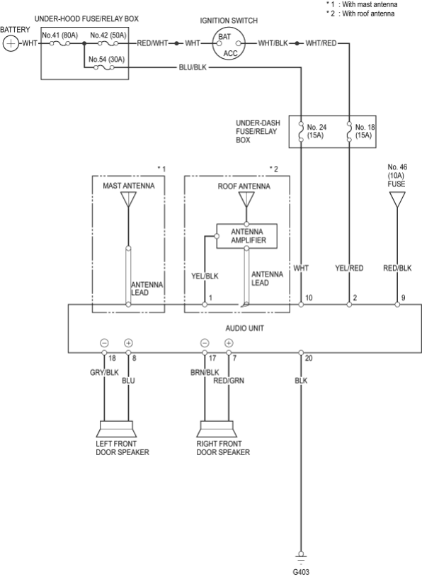
Audio Unit Removal (KY, KT and KQ models)
Audio Unit Connector Terminals Identification (KY, KT and KQ models)
- 1.Remove the centre panel from the dashboard (see section 20).
- 2.Remove the four screws from the bracket.
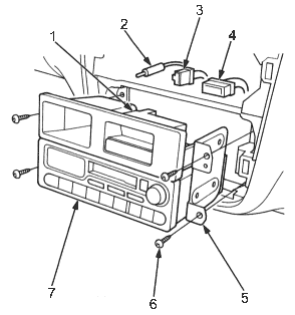
- 1. CLOCK
- 2. ANTENNA LEAD
- 3. 4P CONNECTOR
- 4. 20P CONNECTOR
- 5. BRACKET
- 6. SCREW
- 7. AUDIO UNIT
- 3.Disconnect the 20P connector and the antenna lead from the audio unit, and the 4P connector from the clock.
- 4.Remove the four screws, then remove the audio unit from the bracket.
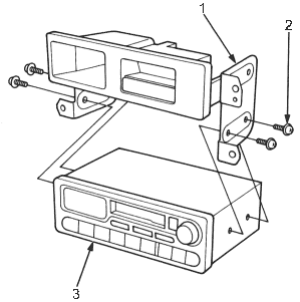
- 1. BRACKET
- 2. SCREW
- 3. AUDIO UNIT
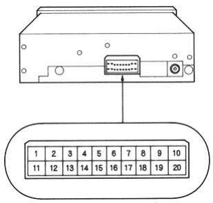
| Cavity | Wire | Connects to |
| 1 | YEL/BLK | Roof Antenna |
| 2 | YEL/RED | ACC (main power supply) |
| 3 | ------------ | Not used |
| 4 | ------------ | Not used |
| 5 | ------------ | Not used |
| 6 | ------------ | Not used |
| 7 | RED/GRN Right Front Door Speaker (+) | |
| 8 | BLU | Left front door speaker (+) |
| 9 | RED/BLK | Lights-on signal |
| 10 | WHT | Constant power (tuning memory) |
| 11 | ------------ | Not used |
| 12 | ------------ | Not used |
| 13 | ------------ | Not used |
| 14 | ------------ | Not used |
| 15 | ------------ | Not used |
| 16 | ------------ | Not used |
| 17 | BRN/BLK | Right front door speaker (-) |
| 18 | GRN/BLK | Left front door speaker (-) |
| 19 | ------------ | Not used |
| 20 | BLK | Ground (G403) |