PDF p. 199 · 4-15
Component Location Index
NOTE: LHD type is shown, RHD type is similar.
IGNITION TIMING CONTROL SYSTEM
- Troubleshooting, section 11
- Idle speed Inspection/Adjustment, section 11
- Inspection and Setting (See Page 4-19)
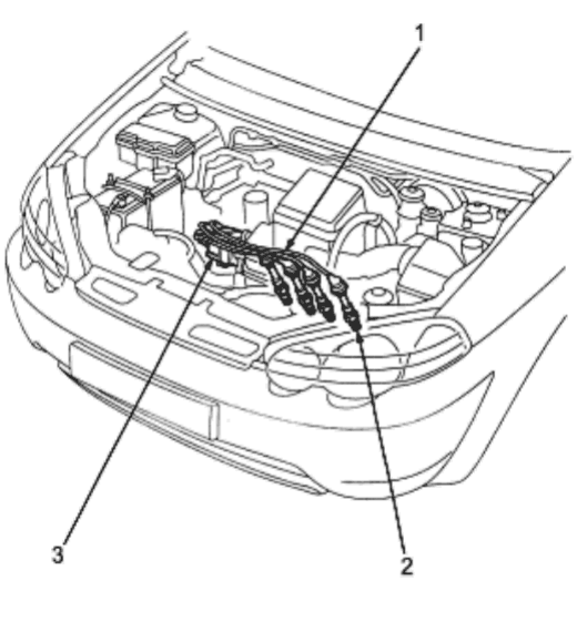
- 1. IGNITION WIRES
Inspection and Test, (See page 4-21) - 2. SPARK PLUGS
Inspection, (See page 4-21) - 3. DISTRIBUTOR
Replacement, (See page 4-18) Overhaul, (See page 4-19)
Ignition Coil Test, (See page 4-20) Ignition Control Module (ICM) Input Test (See page 4-20)
PDF p. 200 · 4-16
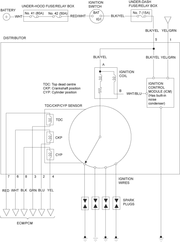
Circuit Diagram
PDF p. 201 · 4-17
Ignition Timing Inspection and Setting
- 1.Check the idle speed, and adjust it if necessary (see section 11).
- 2.Pull out the service check connector 2P (BRN and BLK wires), then connect the SCS short connector (P/N 07PAZ-0010100) to it (see section 11)
- 3.Start the engine. Hold the engine at 3,000 rpm (min.-1) with no load in N or P position, until the radiator fan comes on, then let it idle
- 4.Connect the timing light to the No. 1 ignition wire, then point the light towards the pointer on the timing belt cover.
- 5.
Check the ignition timing in no load conditions:
headlights, blower fan, rear window defogger, and air conditioner are not operating.
Ignition Timing:
12° ± 2° BTDC (RED) during idle in N or P
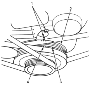
- 1. POINTERS
- 2. CRANKSHAFT PULLEY
- 3. WHT MARK (TDC)
- 4. RED MARK
- 6.If necessary, adjust the ignition timing as follows. Loosen the distributor mounting bolts, and turn the distributor (DI) housing counterclockwise to advance the timing or clockwise to retard the timing.
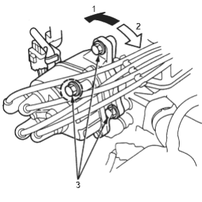
- 1. To ADVANCE
- 2. To RETARD
- 3. MOUNTING BOLTS, 24 Nm (2.4 kgf/m, 17 lbf/ft)
- 7.Tighten the distributor mounting bolts, and recheck the ignition timing.
- 8.Disconnect the SCS short connector from the service check connector.
PDF p. 202 · 4-18
Distributor Replacement
Removal:
- 1.Disconnect the connector from the distributor.
- 2.Disconnect the ignition wires from the distributor ignition (DI) cap.
- 3.Remove the mounting bolts from the distributor, then remove the distributor from the cylinder head.
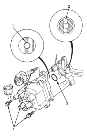
- 1. DISTRIBUTOR END
- 2. CAMSHAFT END
- 3. O-RING. Replace.
- 4. MOUNTING BOLTS. 8 x 1.25 mm, 24 Nm (2.4 kgf/m, 17 lbf/ft)
Installation:
- 1.Bring the No. 1 piston to compression stroke TDC.
- 2.Coat a new O-ring with engine oil, then install it.
- 3.
Align the lug on the end of the distributor and its mating grooves in the camshaft end, then slip the distributor into position.
NOTE: The lug on the end of the distributor and its mating grooves in the camshaft end are both offset to eliminate the possibility of installing the distributor 180° out of time.
- 4.Install the mounting bolts, and tighten them fully.
- 5.Connect the ignition wires to the distributor ignition (DI) cap as shown.
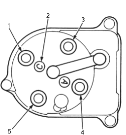
- 1. No. 1
- 2. No. 1 CYLINDER MARK
- 3. No.3
- 4. No. 4
- 5. No.2
- 6.Connect the connector to the distributor.
- 7.Set the ignition timing (see previous page).
- 8.After setting the ignition timing, tighten the mounting bolts.
PDF p. 203 · 4-19
Distributor Overhaul
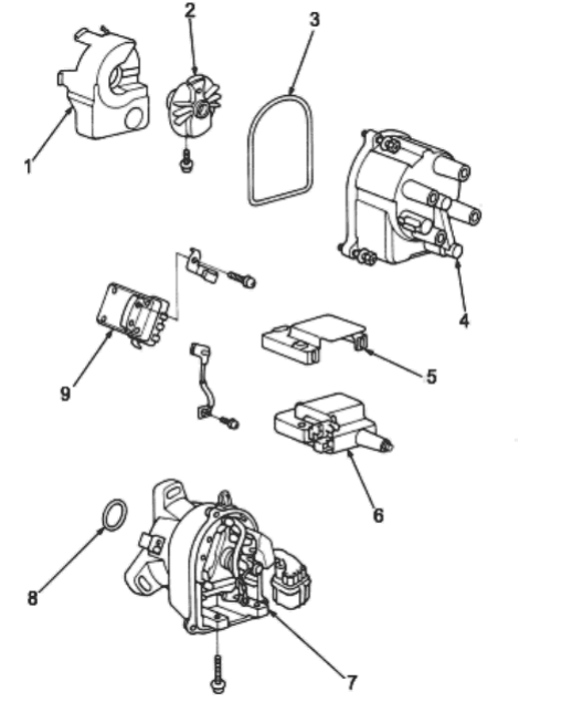
- 1. LEAK COVER
- 2. DISTRIBUTOR IGNITION (DI) ROTOR
- 3. CAP SEAL. Check for damage.
- 4. DISTRIBUTOR IGNITION (DI) CAP Check for cracks, wear, damage and fouling. Clean or replace.
- 5. MAGNETIC SHIELD
- 6. IGNITION COIL
Test, (See page 4-20) - 7. DISTRIBUTOR IGNITION (DI) HOUSING. Check for cracks and damage.
- 8. O-RING. Replace.
- 9. IGNITION CONTROL MODULE (ICM) Input Test, (See page 4-20)
PDF p. 204 · 4-20
Ignition Coil Test
Using an ohmmeter, measure the resistance between the terminals. If the resistance is not within specifications, replace the ignition coil.
NOTE: Resistance will vary with the coil temperature:
specifications are at 20°C (68°F).
Primary Winding Resistance
(Between the A and B terminals):
0.63 - 0.77 ohm
Secondary Winding Resistance
(Between the A and B secondary winding terminals):
12.8 - 19.2 Kohms
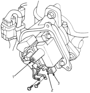
- 1. SECONDARY WINDING TERMINAL
- 2. TERMINAL A (+)
- 3. TERMINAL B (-)
Ignition Control Module (ICM) Input Test
- 1.Remove the distributor ignition (DI) cap, the distributor ignition (DI) rotor and the leak cover.
- 2.Disconnect the wires from the ICM
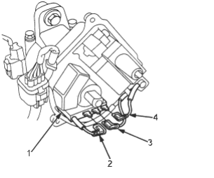
- 1. ICM
- 2. YEL/GRN WIRE
- 3. BLK/YEL WIRE
- 4. WHT/BLU WIRE
- 3.Turn the ignition switch ON (II). Check for voltage between the BLK/YEL wire and body ground. There should be battery voltage.
- If there is no battery voltage, check the BLK/YEL wire between the under-dash fuse/relay box and the ICM.
- If there is battery voltage, go to step 4.
- 4.Turn the ignition switch ON (II). Check for voltage between the WHT/BLU wire and body ground. There should be battery voltage.
- If there is no battery voltage, check:
- the ignition coil.
- the WHT/BLU wire between the ignition coil and the ICM.
- If there is battery voltage, go to step 5.
- If there is no battery voltage, check:
- 5.Check for continuity on the BLU wire between the test tachometer connector and the ICM. There should be continuity.
- 6.Check for continuity on the BLU wire to body ground. There should be no continuity.
- 7.If all tests are normal, replace the ICM.
PDF p. 205 · 4-21
Ignition Wire Inspection and Test
- 1.Carefully remove the ignition wires by pulling on the rubber boots. Do not bend the wires; you might break them inside.
- 2.Check the condition of the ignition wire terminals. If any terminal is corroded, clean it, and if it is broken or distorted, replace the ignition wire.
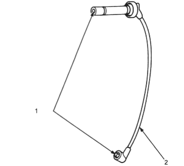
- 1. Check for broken, corroded, and bent terminals.
- 2. IGNITION WIRE
- 3.
Connect the ohmmeter probes and measure resistance.
Ignition Wire Resistance
25 kohm max. at 20°C (68°F)
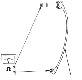
- 1. IGNITION WIRE
- 4.If the resistance exceeds 25 kohm, replace the ignition wire.
Spark Plug Inspection
- 1.Inspect the electrodes and ceramic insulator for:
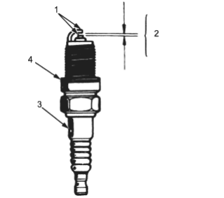
- 1. Worn or deformed electrodes
- 2. ♦ Improper gap
♦ Oil-fouling
♦ Carbon deposits
♦ Cracked centre electrode insulator - 3. Cracked insulator
- 4. Damaged gasket
Burned or worn electrodes may be caused by:
- Advanced ignition timing
- Loose spark plug
- Plug heat range too hot
- Insufficient cooling
Fouled plug may be caused by:
- Retarded ignition timing
- Oil in combustion chamber
- Incorrect spark gap
- Plug heat range too cold
- Excessive idling/low speed running
- Clogged air cleaner element
- Deteriorated ignition wires
PDF p. 206 · 4-22
- 2.Check the electrode gap.
- Adjust the gap with suitable gapping tool.
Electrode Gap
Standard 1.1 - 8.1 mm (0.043 - 8.004 in)
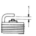
- 1. 1.1 mm (0.043 in)
- Replace the plug if the centre electrode is rounded as shown below:
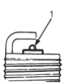
- 1. ROUNDED ELECTRODE
Spark Plugs
ZFR5J-11 (NGK) KJ16CR-L11 (DENSO)
- 3.Apply a small quantity of anti-seize compound to the plug threads, and screw the plus into the cylinder head finger-tight. Then torque then to 18 Nm (1.8 kgf/m, 13 lbf/ft).