PDF p. 190 · 4-6
NOTE: The air temperature must be between 15 and 38° C (59 and 100°F) before testing.
Recommended Procedure:
- Use starter system tester.
- Connect and operate the equipment in accordance with the manufacturer’s instructions.
- Test and troubleshoot as described.
Alternate Procedure:
- Use the following equipment:
- Ammeter, 0 - 400 A
- Voltmeter, 0 - 20 V (accurate within 0.1 volt)
- Tachometer, 0 -1,200 rpm (min-1)
- Hook up a voltmeter and ammeter as shown.
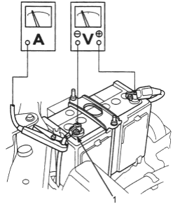
- 1. NEGATIVE TERMINAL
NOTE: After this test, or any subsequent repair, reset the ECM/PCM to clear any codes (see section 11).
Check the Starter Engagement:
- 1.Remove the No. 59 (15 A) fuse from the under-hood fuse/relay box.
- 2.Turn the ignition switch to START (III) with the shift lever in N or P position. The starter should crank the engine.
- If the starter does not crank the engine, go to step 3.
- If it cranks the engine erratically or too slowly, go to “Check for Wear and Damage” on the next page.
- 3.
Check the battery, battery positive cable, ground, starter cut relay, and the wire connections for looseness and corrosion. Test again.
If the starter still does not crank the engine, go to step 4.
- 4.Unplug the connector (BLK/WHT wire and solenoid terminal) from the starter.
- 5.
Connect a jumper wire from the battery positive (+) terminal to the solenoid terminal.
The starter should crank the engine.
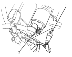
- 1. BLK/WHT WIRE
- 2. SOLENOID TERMINAL
- If the starter still does not crank the engine, remove it, and diagnose its internal problem.
- If the starter cranks the engine, go to step 6.
- 6.Check the ignition switch (see section 23).
- 7.Check the starter cut relay (see section 23).
- 8.Check the immobiliser system (see section 23).
- 9.Check the A/T gear position switch (see section 14).
- 10.Check for an open in the wire between the ignition switch and starter.
PDF p. 191 · 4-7
Check for Wear and Damage
The starter should crank the engine smoothly and steadily. If the starter engages, but cranks the engine erratically, remove it, and inspect the starter drive gear and torque converter ring gear for damage.
Check the drive gear overrunning clutch for binding or slipping when the armature is rotated with the drive gear held. If damaged, replace the gears.
Check Cranking Voltage and Current Draw
Cranking voltage should be no less then 8.5 volts. Current draw should be no more than 350 amperes.
If cranking voltage is too low, or current draw too high, check for:
- dead or low battery.
- open circuit in starter armature commutator segments.
- starter armature dragging.
- shorted armature winding.
- excessive drag in engine.
Check Cranking rpm
Engine speed during cranking should be above 100 rpm (min-1).
If speed is too low, check for:
- loose battery or starter terminals.
- excessively worn starter brushes.
- open circuit in commutator segments.
- dirty or damaged helical splines or drive gear.
- defective drive gear overrunning clutch.
Check Starter Disengagement
With the shift lever in N or P position, turn the ignition switch to START (III), and release to ON (II).
The starter drive gear should disengage from the torque converter ring gear when you release the key.
If the drive gear hangs up on the torque converter ring gear, check for:
- solenoid plunger and switch malfunction.
- dirty drive gear assembly or damaged overrunning clutch.
Starter Solenoid Test
- 1.Check the hold-in coil for continuity between the S terminal and the armature housing (ground). The coil is OK if there is continuity.
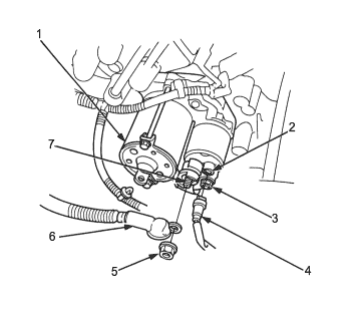
- 1. ARMATURE HOUSING (GROUND)
- 2. S TERMINAL
- 3. M TERMINAL
- 4. BLK/WHT WIRE
- 5. B TERMINAL MOUNTING NUT, 9 Nm (0.9 kgf/m, 7 lbf/ft)
- 6. STARTER CABLE
- 7. B TERMINAL
- 2.Check the pull-in coil for continuity between the S and M terminals. The coil is OK if there is continuity.