PDF p. 1180 · 23-D-14
NOTE: Before testing check for:
- Blown No. 4 (10A) fuse in the under-dash fuse/relay box.
- Bent, loose or corroded terminals.
- 1.Disconnect the 3P connectors from each headlight adjuster unit.
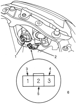
- 1. HEADLIGHT ADJUSTER UNIT
- 2. 3P CONNECTOR
- 3. YEL/BLK
- 4. BLK
- 5. YEL/BLU
- 6. Wire side of female terminals
- 2.
Check for continuity between the No. 3 (BLK) terminal and body ground.
There should be continuity.
- If there is no continuity, check for:
- An open in the BLK wire
- Poor ground (G201, G202, G301).
- If there is continuity, go to step 3.
- If there is no continuity, check for:
- 3.
Check for voltage between the No. 1 (YEL/BLK) terminal and body ground with the ignition switch ON (II).
There should be battery voltage.
- If there is no battery voltage, check for an open in the YEL/BLK wire.
- If there is battery voltage, go to step 4.
- 4.Check for continuity between the No. 2 (YEL/BLU) terminal and body ground in any switch position. There should be continuity.
- If there is no continuity, check for:
- An open in the YEL/BLU wire
- Faulty headlight adjuster switch.
- If there is continuity, go to step 5.
- If there is no continuity, check for:
- 5.
If all input tests prove OK, but the headlight adjuster does not work, check for frozen, stuck or improperly installed headlight adjuster unit.
If the mechanical check is OK, replace the headlight adjuster unit.
- 6.After installing, recheck the system.