PDF p. 1121 · 23-B-4
SRS components are located in this area. Review the SRS component locations, precautions and procedures in the SRS section (24) before performing repairs or service.
- 1.Disconnect both the negative cable and positive cable from the battery.
- 2.Remove the driver's lower pocket (see section 20).
- 3.Disconnect the 7P connector from the under-dash fuse/relay box.
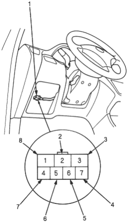
Wire side of female terminals
- 1.7P CONNECTOR
- 2.BLU/WHT
- 3.WHT
- 4.BLU/WHT
- 5.WHT/BLK
- 6.YEL
- 7.BLK/YEL
- 8.BLK/WHT
- 4.Check for continuity between the terminals in each switch position according to the table.
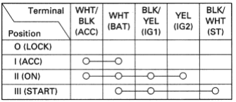
- 5.If continuity checks do not agree with the table, replace the steering lock assembly.