PDF p. 1083 · 22-28
NOTE: LHD type is shown, RHD type is similar.
- 1.If the compressor is marginally operable, run the engine at idle speed and let the air conditioning work for a few minutes, then shut the engine off.
- 2.Disconnect the negative cable from the battery.
- 3.Discharge the refrigerant (See Page 22-38).
- 4.Remove the bolts, then disconnect the suction and discharge lines from the compressor. Plug or cap the lines immediately after disconnecting them to avoid moisture and dust contamination.
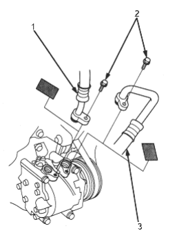
- 1. DISCHARGE LINE
- 2. 6 x 1.0 mm, 9.8 Nm (1.0 kgf/m, 7.2 lbf/ft)
- 3. SUCTION LINE
- 5.Loosen the centre nut of the idler pulley and the adjusting bolt, then remove the A/C compressor belt from the pulleys. If necessary, remove the power steering pump belt (see section 17) and the mounting bolts from the left front mount, then remove the A/C compressor belt through the gap between the body and the left front mount.
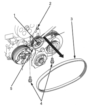
- 1. CENTRE NUT
- 2. ADJUSTING BOLT
- 3. A/C COMPRESSOR BELT
- 4. 10 x 1.25 mm, 44 Nm (4.5 kgf/m, 33 lbf/ft)
- 5. LEFT FRONT MOUNT
- 6.Disconnect the compressor clutch connector, then remove the mounting bolts and the compressor.
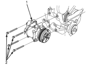
- 1. COMPRESSOR
- 2. 8 x 1.25 mm, 24 Nm (2.4 kgf/m, 17 lbf/ft)
PDF p. 1084 · 22-29
- 7.If necessary remove the compressor bracket as follows:
- Remove the nut and washer from the left front mount. When tightening the nut to the left front mount, make sure the washer is set properly on the left front mount as shown.
- Remove the mounting bolts and the compressor bracket.
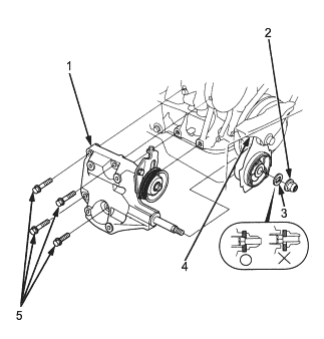
- 1. COMPRESSOR BRACKET
- 2. 12 x 1.25 mm, 59 Nm (6.0 kgf/m, 43 lbf/ft)
- 3. WASHER
- 4. LEFT FRONT MOUNT
- 5. 1.0 x 1.25 mm, 44 Nm (4.5 kgf/m, 33 lbf/ft)
- 8.Install in the reverse order of removal and note the following items:
- If you are installing a new compressor, drain all the refrigerant oil form the removed compressor and measure its volume. Subtract the volume of drained oil from 130 ml ( 4 1/3 fl. oz, 4.6 Imp. oz): the result is the amount of oil you should drain from the new compressor (through the suction fitting).
- Replace the O-rings with new ones at each fitting and apply a thin coat of refrigerant oil before installing them. Be sure to use the correct O-rings for HFC-134a (-134a) to avoid leakage.
- Use refrigerant oil (KEIHIN, SP-10) for HFC-134a KEIHIN spiral type compressors only.
- To avoid contamination, do not put the oil back in the container once dispensed and never mix it with other refrigerant oils.
- Immediately after using the oil, replace the cap on the container and seal it to avoid moisture absorption.
- Do not spill the refrigerant oil on the vehicle; it may damage the paint; if the refrigerant oil contacts the paint, wash it off immediately.
- Adjust the A/C compressor belt (See Page 22-35) and the power steering pump belt (see section 17).
- Charge the system (See Page 22-40) and test its performance (See Page 22-42).