PDF p. 1081 · 22-26
NOTE: LHD type is shown, RHD type is symmetrical.
- 1.Discharge the refrigerant (See Page 22-38).
- 2.Remove the bolts, then disconnect the suction and receiver lines from the evaporator. Plug or cap the lines immediately after discharging them to avoid moisture and dust contamination.
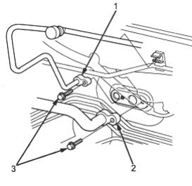
- 1. RECEIVER LINE
- 2. SUCTION LINE
- 3. 6 x 1.0 mm, 9.8 Nm (1.0 kgf/m, 7.2lbf/ft)
- 3.Remove the glove box (see section 20).
- 4.Disconnect the connectors from the A/C thermostat and the recirculation control motor and the drain hose. Then remove the clip, wire harness clip, the self tapping screws, the mounting bolts, the mounting nut and the evaporator.
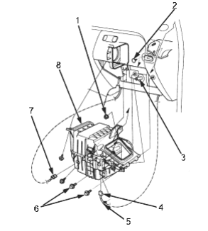
- 1. 6 x 1.0 mm, 9.8 Nm (1.0 kgf/m, 7.2 lbf/ft)
- 2. CLIP
- 3. DRAIN HOSE
- 4. CONNECTOR
- 5. CLIP
- 6. 6 x 1.0 mm, 9.8 (1.0 kgf/m, 7.2 lbf/ft)
- 7. CONNECTOR
- 8. EVAPORATOR
- 5.Install in the reverse order of removal and note the following items:
- If you are installing a new evaporator, add refrigerant oil (KEIHIN Sp-10) (See Page 22-24).
- Replace the O-rings with new ones at each fitting and apply a thin coat of refrigerant oil before installing them. Be sure to use the right O-rings for HFC-134a (R-134a) to avoid leakage.
- Immediately after using the oil, replace the cap on the container and seal it to avoid moisture absorption.
- Do not spill the refrigerant oil on the vehicle; it may damage the paint, wash it off immediately.
- Make sure that there is no air leakage.
- Charge the system (See Page 22-40) and test its performance (See Page 22-42).